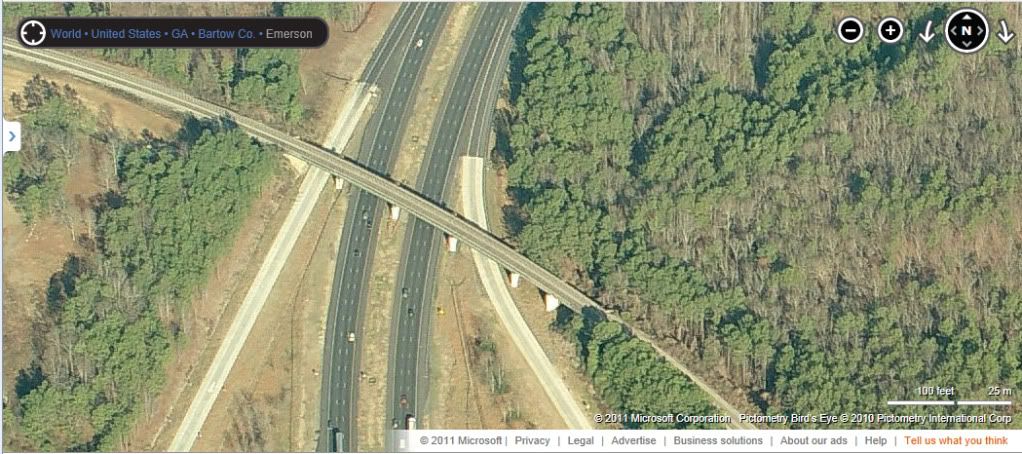
To spice up the scenery and add operational realism along the southern end of the layout, I added a working grade crossing where Allatoona Road crosses the tracks at milepost WA 39.6 on the CSX W&A subdivision. As the above video shows, the grade crossing functions just as it does on the prototype: as a train approaches, the lights begin flashing and the gates slowly lower across the roadway. After the train clears, the gates slowly raise and the lights go dark. The process repeats itself every time a northbound or southbound train passes through the scene, keeping the imaginary N-scale inhabitants out of harms way.
The signals used in this project are NJ International #2164. These signals are almost an exact match for the ones used at the real crossing and feature large modern "bug eye" flashers in both directions, crossbucks, and moving bar-arm gates with red stripes. The signal flashers on the signal upright are LEDs pre-wired with dropping resistors; however, the lights on the gates are molded on and do not operate. These signals, which are molded brass, come packaged as a pair and are super nice models. Plus, at about $30 they are also a great value.
» FlashersThe flashers are driven by a Digitrax DS-64 quad stationary decoder. The DS-64 is commonly used to operate turnout motors, but it has a nifty feature that allows the outputs to alternate at a rate that is ideal for crossing flashers. The DS-64 can also be connected to the Digitrax Loconet, which means it can operate in conjunction with Digitrax block detection so the signals will activate when a train occupies the crossing.
- I strongly recommend testing the flashers before installing the signals on the layout since it will be much more difficult to replace a set of defective signals later on. To do this, configure one set of outputs on the DS-64 to alternate/flash when activated (refer to your Digitrax instructions for the steps necessary to do this).
- Connect the signals to the DS-64 as indicated in the Digitrax instructions. Using your throttle, open and close the switch address for the appropriate set of outputs on the DS-64. The lights should flash and then go off as you open and close the switch. In this photo, you can see one of the signals being tested with the DS-64:

- After mounting the signals on the layout, simply connect the wires to the DS-64 below the layout just as you did when you tested the flashers before installation. When wiring the signals, be sure that both signals flash with each other and not against each other. In other words, when approaching the crossing in a vehicle on the road, both flashers should be flashing in unison: the right flasher should be lit, then the left, and so on. To see this in action, watch the video above and pay close attention to the flashing pattern of both signals as the gates are lowering. If your flashers are not doing this, simply reverse the connection to the DS-64 for one of the signals.
» Signals
- As packaged, the gates have a short actuating wire attached to them. You can see these wires in the photo above where the flashers are being tested with the DS-64. I needed a much longer actuation wire, so I replaced the factory wires with some longer handmade ones. I removed the factory installed wires with a small pair of clippers. WARNING: These signals are very delicate, so use care when using the clippers to removing the actuating wires.
- Drill a pair of holes at each signal location: a large hole for the base of the signal and a smaller hole for the actuating wire attached to the gate. To locate the smaller hole, I placed the signal in the larger hole and marked a spot below where the actuating wire attaches to the gate:

- Mount the signals in the larger hole using your glue of choice; I used white glue. Be sure to use care and not get any glue on or around the moving parts of the signals.
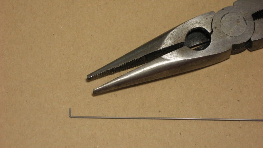
- With the signals mounted, I went ahead and installed the new actuating wires for the gates. To create the actuating wires, I cut a piece of .025 steel wire to about 12" in length. Don't worry about the exact length, you just want enough so that it reaches the Tortoise actuators that will be mounted below the layout. I made a small 90 degree bend in one end using a pair of needle nose pliers:

- To install the actuator wire, feed the straight end down through the hole in the layout from above and carefully slip the bent end through the hole in the end of the gate:

- With the actuator wire attached to the hole in the gate, it is now basically hanging down through the layout down below the benchwork. You should be able to reach under the layout and move the actuator wire up and down to make sure the gates lower and raise as they should.
» GatesBy far the most complex and difficult phase of the signal installation is getting the crossing gates to actually work along with the flashers. In fact, the installation of the gate mechanism was probably the most tedious and frustrating time I have ever experienced on the layout. There were several times I considered replacing the signals with ones that did not have crossing gates. However, patience eventually prevailed and I can now say that the outcome was well worth the effort. Watching the gates lower and raise each time a train passes really brings the whole scene to life.
There are a few components that you need to buy to make the crossing gate magic work:
- (1) Circuitron 800-6000 "Tortoise" Slow Motion Switch Machine
- (1) Circuitron 800-8100 Remote Signal Activator (RSA)
- (1) Circuitron 800-8101 Extra cable & actuator for RSA
The best advice I can give for working with the RSA is to read the instructions from beginning to end. Then read them again. And again, and again, and again. The first time you will be saying "What the...?" but after a while something will click and you will realize the RSA is a brilliant little piece of hardware.
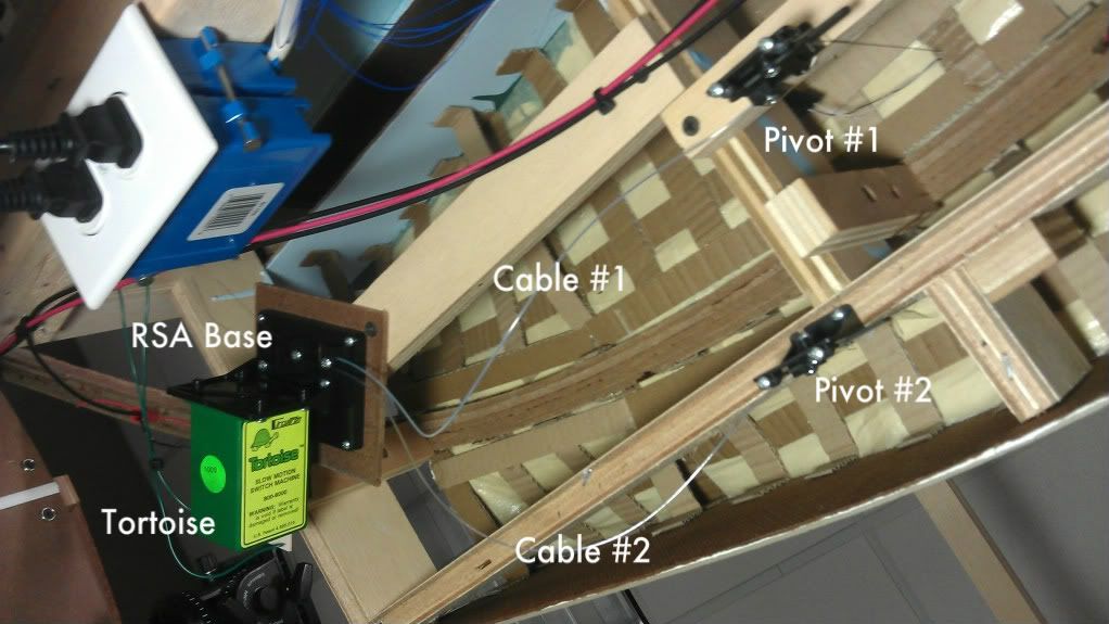
Basically, the Tortoise is attached to a slider on the base of the RSA which in turn is attached a pair of cables that fan out to a pair of remote pivots mounted below the crossing gates on the layout. These remote pivots are connected to the actuator wires that we previously attached to our crossing gates. When the Tortoise moves, the slider moves back-and-forth, causing the cables to extend and retract, which makes the pivots rotate, which cause the actuating wires to lower and raise the crossing gates. Magic.
- To begin, select a location under the layout where the RSA will be mounted. You want to pick a location out of the way from the crossing gates as to not interfere with the mounting location of the pivots, but close enough so the cables from the RSA to the pivots will not need to be excessively long. The cables are flexible so they can curve, but don't make the curves too tight or the cables will bind when operated. Consult the RSA instructions for the specific limitations of the cables. Be sure to allow enough room to accommodate the Tortoise motor.
- Mount the RSA below the layout according to the RSA instructions.
- Mount the pivots below the crossing gates according to the RSA instructions. The actuating wires hanging down from the gates will determine where the pivots must go.
- Connect the cables between the RSA and the pivots according to the RSA instructions.
- Clip the actuating wires (hanging from the crossing gates) to an appropriate length and attach to the pivots according to the RSA instructions.
- Attach the Tortoise switch motor to the RSA according to the RSA instructions.
- Wire the Tortoise to one of the sets of outputs on the DS-64. Consult the Digitrax instructions for the specifics of this step.
- Using the switch address of the DS-64 outputs, use your throttle to operate the Tortoise switch motor. The entire apparatus should function as described above.
- The pivots have adjustment screws that allow you to control their range of motion. If the crossing gates do not raise or lower to their correct positions, play with the adjustment screws until the gates end up in their desired positions.
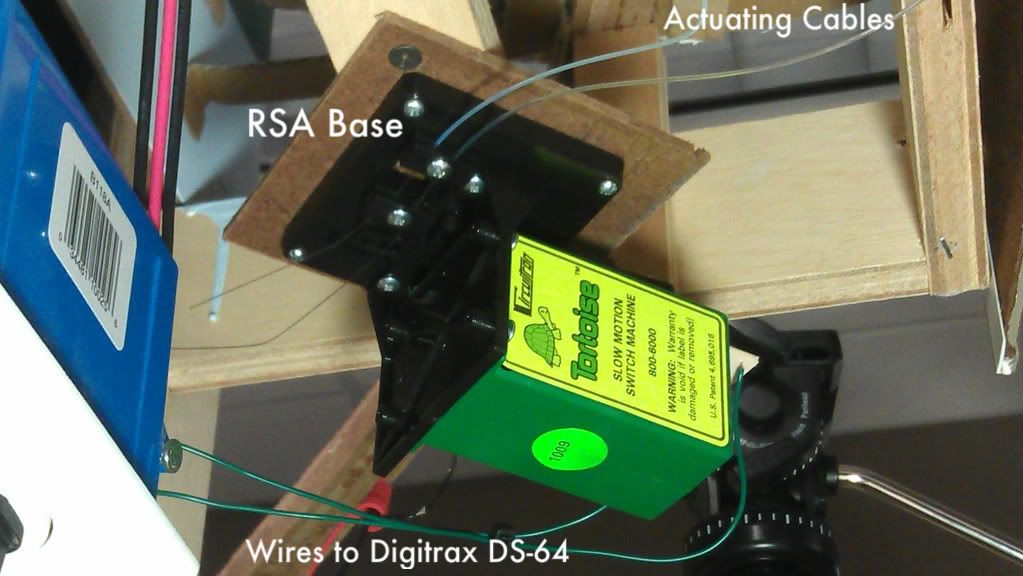
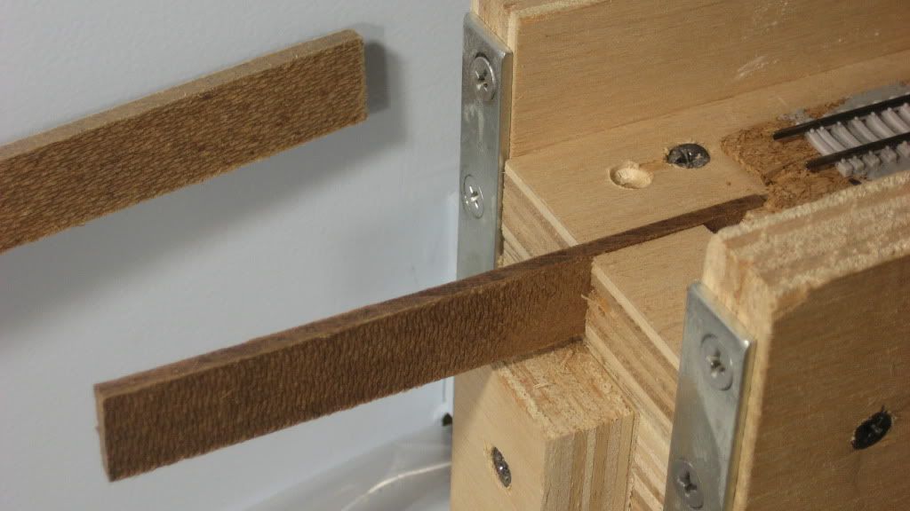
The following photos show the overall Circuitron RSA installation, looking up from below the layout. In the first photo, notice how a 1x3 crossmember has been added to mount the RSA base and a 1x2 crossmember has been added to mount pivot #1:

RSA base details:

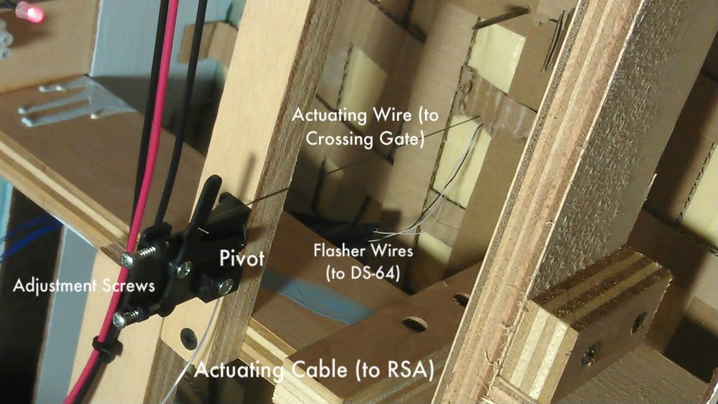
Pivot details:

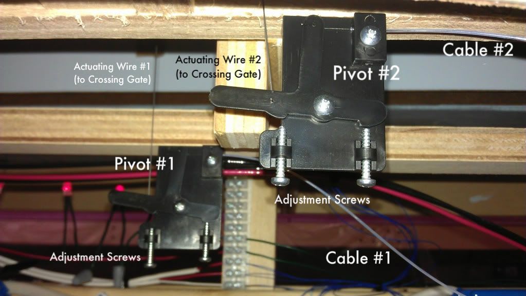
Pivot side view:

.