Sunday, December 18, 2011

Layout Progress as of 12/18/2011

While working on the Etowah River scene, I realized some additional benchwork needs to be added around the bridge before track can be installed. Before adding the extra support, however, I needed a way to see exactly where it has to go. To do this, I created some full-size mockups of the bridge scene. The actual bridge is comprised of seven deck girder bridge sections supported by concrete piers. I will eventually be using Micro Engineering 80' ballasted deck bridges supported by cast plaster or cement piers. The following two photos show the mockups I did. The first photo shows the complete non-compressed bridge (seven sections), while the second photo shows a compressed version of the scene with only six sections (one section over the river removed):


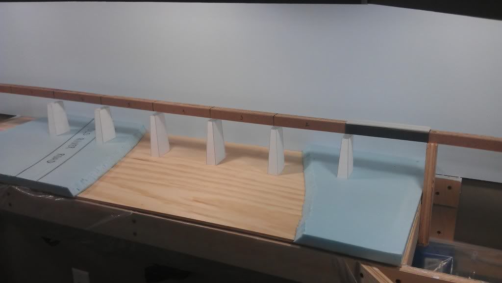
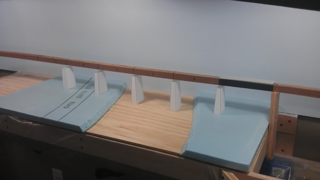
I wanted to try out the compressed version because I believed the full size bridge would be too big. Also, six 80' deck bridge sections comes out to an even 36" in N-scale, which means I could use one 3-foot length of aluminum U-channel to be the supporting backbone of the bridge. However, when looking at the two photos the river just seems too narrow in the compressed version. I am also considering using a compressed bridge with the full-size river; in this case, the road would be eliminated. This option is probably not going to be selected because that road is one of my first ever railfanning locations and is a significant reason why I chose to model this area in the first place.

Whatever option I choose, the mockups are a quick way to visualize a completed scene without too much effort (time or money).

.