This post takes a highly detailed step-by-step look at how I built the dropdown gate across the doorway on the lower level of my N-Scale CSX Dixie Line layout. The gate will provide two functions: 1) allow trains to get from one side of the doorway to the other and 2) allow people to enter and exit the layout room easily. While the upper level can be ducked under fairly easily, asking a person to duck under the lower level would just be too much to ask!
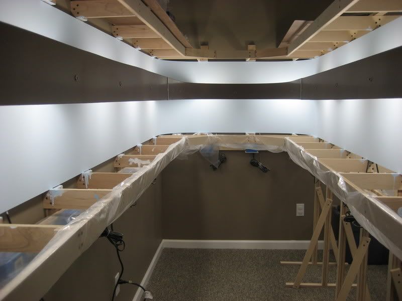
Step 1 Looking back at an earlier picture of the layout, you can see where the gate will go. The distance across the doorway (between the wall bracket arms on either side) is 43.5", so the length of the bridge will be 46.5" to accommodate for the 3/4" width of each wall bracket arm and an additional 3/4" cleat on each bracket arm that the ends of the bridge will rest on:
 Step 2
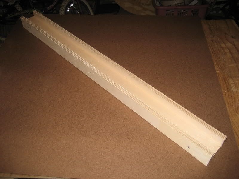
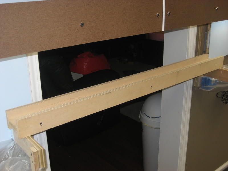
 The bridge span is constructed of three 1x3" boards ripped from 3/4" birch plywood and cut to a length of 46.5". The three boards are held together temporarily using three drywall screws on each side so the assembly can be test fitted on the layout:
 Step 3
 A closer look at the end of the bridge span reveals the sideways I-beam arrangement of the three 1x3" boards. There are a few reasons I chose this construction for the bridge span:
1) The horizontal bridge deck will provide a nice wide, level surface for mounting the roadbed and track.
2) The vertical sides will prevent sag of the bridge deck.
3) The vertical sides will act as guard rails to prevent a derailed train from "taking the plunge."
4) When the vertical sides rest on the wall bracket arms, the surface of the bridge deck will be 1.5" above the tops of the wall bracket arms, which is an exact match to the top surface of the spline roadbed that will be used on the lower level of the layout.
 Step 4
 The backdrop on the right side of the doorway bends forward so the wall switches to the room lights can be accessed. This required the back side of the bridge to be notched so it would fit on the layout as far back from the front of the benchwork as possible. The track in this area runs quite close to the backdrop to accommodate the turnouts for the siding and house track at North End Emerson:

 Step 5
 The vertical sides of the bridge span rest atop the wall bracket arms on either side of the doorway. However, I had to build some "piers" on both wall bracket arms so there would be a good place to fasten the bridge ends and add support. I built the piers using scraps of the same 1x3" boards used to build the bridge span (this picture shows the left side pier; the right side is identical):
 Step 6
 These pictures show how the bridge span sits atop the bridge piers. I have fastened the bridge span to the pier using a pair of 2" angle brackets. The angle brackets hold the bridge span in place and also resist the downward forces on the cantilevered section of the bridge span when the gate is opened (these pictures show the left side pier; the right side is identical):

 Step 7
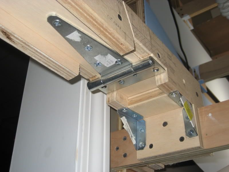
 I cut notches in the bottom of each bridge side so that the 4" gate hinge could be attached to the bottom of the bridge span using eight 3/4" #10 wood screws. Note that the square side of the hinge is actually screwed into the bridge deck
and the bridge sides. I used a jigsaw to make these cuts, which explains why they are so ragged and the top of the notch does not line up with the bottom of the bridge deck as it should:

 Step 8
 I marked the locations of the diagonal cuts on each board of the bridge span and made the cuts using a chop saw. As I was about to make the cuts, I remembered to mark each board so I would know how the pieces would go back together:
 Step 9
 I reassembled the bridge assembly and held my breath as I put it in place...everything fit correctly!
 Step 10
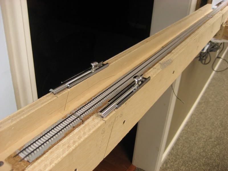
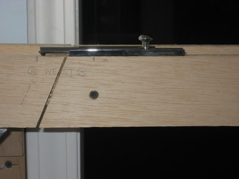
 I used a sliding door bolt as the locking mechanism on the gate. The next few pictures show how this was installed. Note that the sliding part of the bolt actually rests on top of a drywall screw on the other side of the gap. This is needed to keep the bridge deck at the same height on both sides of the gap. Note how the diagonal cuts in the bridge sides do not line up with the diagonal cut bridge deck--this results in the bridge deck forming a "tongue" that fits between the bridge sides when in the closed position to maintain side-to-side alignment:


 Step 11
 A second door bolt was required to keep the bridge deck level when the gate is locked closed:
 Step 12
 I used 4" mending plates strengthen the attachment of the bridge piers to the wall bracket arms:

 Step 13
 I am using laminated spline sub-roadbed for the layout. After the gate was completed, I realized I failed to notch the ends of the bridge deck so a center spline of the roadbed could be attached to the ends of the bridge. I disassembled the bridge and cut 1/8" notches 1.5" deep into each end of the bridge deck. Since the splines will be 1/8" wide and 3/4" tall, these notches will keep the bridge and the sub-roadbed in perfect alignment:

 Completed Gate
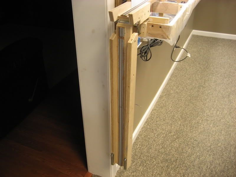
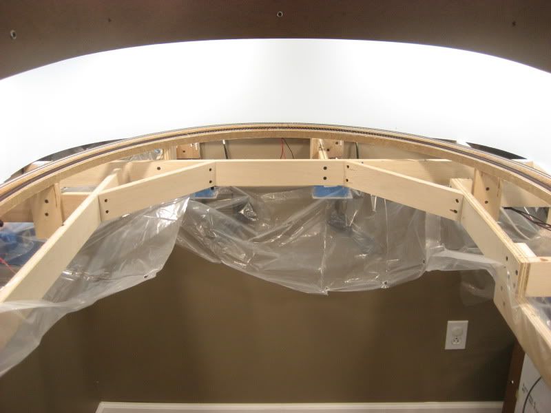
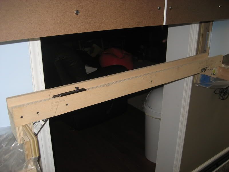
 Finally, a few shots of the completed gate in the open and closed positions:


.

















 Posts
Posts


