One of the primary design goals for the layout is to have a fully functional Computerized Traffic Control (CTC) system. Looking even farther into the future, some degree of layout automation is desired. To meet these objectives, a DCC system with fully functional block detection is a must. Since my DCC system is a Digitrax Super Chief, the
Digitrax BDL168 was a natural choice for block detection. This board provides for detection of 16 individual blocks and reports block occupancy via messages over Loconet. A personal computer can then be connected to Loconet and receive these messages. With appropriate software, a complete operational CTC system is possible. My software of choice is JMRI, which I will describe below.
» How it works
The following diagram shows how the Digitrax BDL168 is connected to the layout:
The above diagram shows the connections for a typical passing siding track arrangement on the layout. Each turnout is a separate detection section, as is the mainline and the passing siding. Therefore, a passing siding on the layout will consume four of the 16 total detection sections on a BDL168. I anticipate the need for three BDL168 boards on the layout (one for each of the three levels). Only signaled track will be detected; non-signaled tracks such as spurs and industrial sidings will bypass the BDL168.
The following photo shows the first BDL168 installed on the layout:
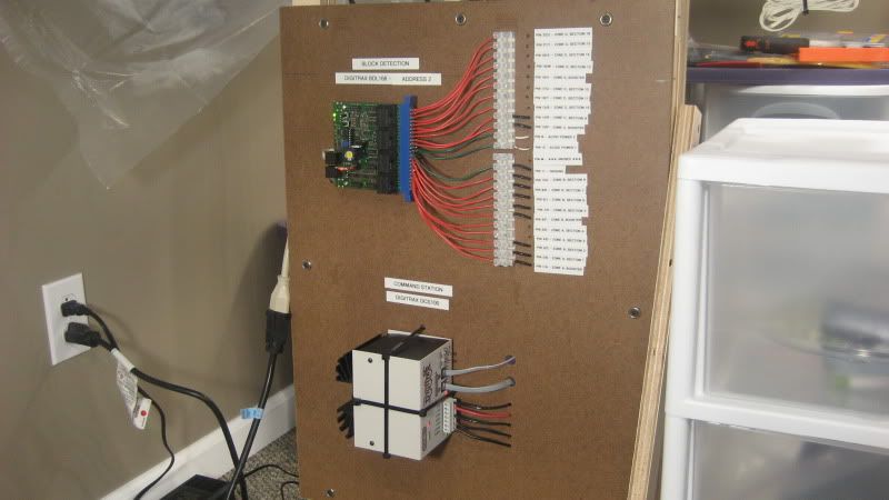
Astute viewers may note that the BDL168 is connected directly to the DCS100 booster below, which differs from the diagram above. The diagram shows a Digitrax PM42 between the two, but since I only have about 30 feet of mainline in place, I have yet to justify the expense of a power management board.
Digitrax supplies a handy worksheet for you to record information on how your BDL168 boards have been configured. Here is one that I have filled out for the first block detection board installed on the Dixie Line:
In the above worksheet, the detection sections highlighted in yellow represent track that has already been installed on the layout. Other detection sections shown in the worksheet are planned for future use. Basically, the Emerson section of the layout is the proving grounds where I can work on ideas that will eventually be expanded to the entire layout.
I have set the address of this BDL168 to 101. By default, the board is shipped from the factory with an address of 1. I changed the address to a higher number so that there will be no conflicts with other devices such as turnouts that will be in the lower address range.
» JMRI
I have begun to use the
Java Model Railroad Interface (JMRI) software to control the layout. The computer is connected to Digitrax Loconet via a LocoBuffer USB, which in turn lets JMRI talk to Loconet. JMRI receives messages from Loconet that tell the software what is happening on the layout, and JMRI sends messages to Loconet to make things happen on the layout such as changing a turnout, setting a signal, or controlling a train.
In JMRI, I use the
PanelPro application to setup communication with LocoNet. In PanelPro, block detection is facilitated by using objects known as
sensors. A sensor is
active when a block is occupied and
inactive when a block is clear. In JMRI, you can define a sensor for every detection section on all of your BDL168 boards. The following screen shot shows how I have setup the sensors for my first BDL168 in JMRI:

Ignore the first line in the table; that is some fast clock sensor that JMRI automatically created for some reason that I don't yet know. However, the remaining entries show the 16 sensors that correspond to the 16 detection sections on the BDL168 board that I described above.
Earlier I mentioned that I set the address of the BDL168 board to 101. The board address determines the address for the corresponding JMRI sensors. The formula used to calculate the address of a BDL168 sensor in JMRI is as follows:
(board address - 1) * 16 + detection sectionJMRI also requires the sensor address to be prefixed with LS when using Digitrax Loconet, so the 16 detection sections on the BDL168 will be represented in JMRI by sensors LS1601 to LS1616. A second BDL168 with a board address of 102 would be represented in JMRI by sensors LS1617 to LS1632 and so on.
Notice that two of the sensors, LS1606 and LS1607, are shown as active in the above table because there are actually trains sitting on those tracks. Moving one of those trains to another track will cause the appropriate sensors to activate and deactivate accordingly. This is super cool stuff, albeit in a super nerdy way!
OK, so we have Digitrax DCC block detection installed on the layout, we have JMRI talking to Digitrax Loconet, and we have sensors setup in JMRI that are obviously working. This is all fine and dandy, but how do a bunch of invisible computer bits turning on an off as trains move around the tracks actually contribute to the operation of the layout? This is where JMRI Panel Pro really pays off: the ability to build fully functional panels that allow you to operate the layout. Here is the CSX Dixie Line panel so far:

The sensors in the above panel are represented by the red lights: illuminated lights show occupied blocks while dark lights show clear blocks. I added the sensors to the panel by selecting the appropriate entries from the sensor table in the panel editor window. The sensors on the mainline above from left to right are LS1609, LS1608, LS1607 (the siding/lower track), LS1606 (the mainline/upper track), LS1605, and LS1604. Notice that the sensors LS1606 and LS1607 are illuminated since there are trains sitting on both of those tracks.
The graphics are based on the old USS CTC panel designs; although they are quite retro looking and I model the modern era, I actually like they way they look and am sticking with them for now. JMRI provides a graphics library to use when creating panels, so it should be fairly easy to switch to different graphics if I ever desire to do so. This particular panel so far looks very simple since I only have about 30 feet of mainline and one passing siding installed. However, the small size of the panel makes it easy to use and is an ideal learning tool. Plus, there is actually a lot of stuff on this panel, including two turnouts (that I want to control remotely via the panel) and six blocks. A lot of stuff to play around with but still small enough not to overwhelm a novice JMRI user such as myself.
Eventually, this panel will evolve into a fully functional CTC panel. For now, I can run trains and watch the sensor lights turn on and off. Although it seems quite simple on its own, this block detection implementation is actually the foundation that will be used for all future CTC and layout automation.
.
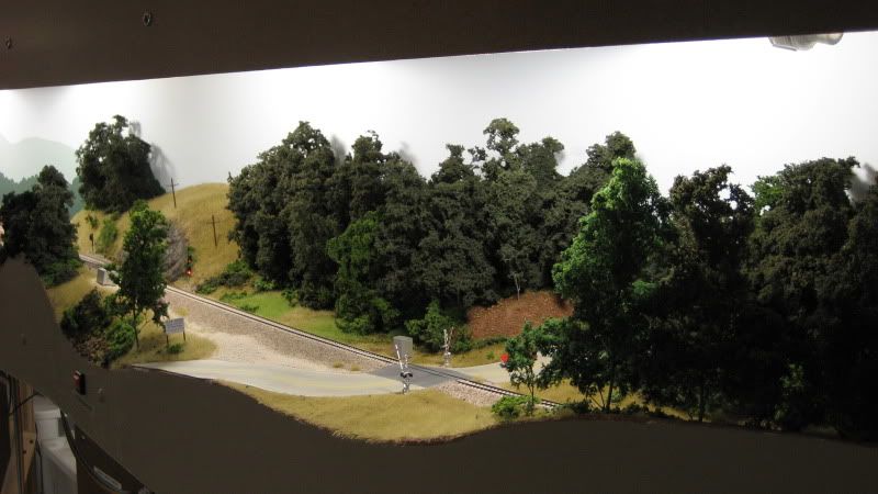
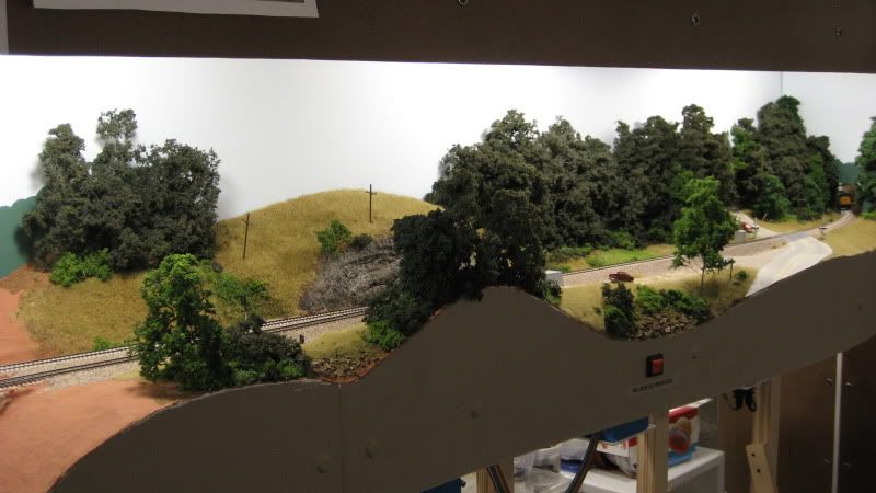

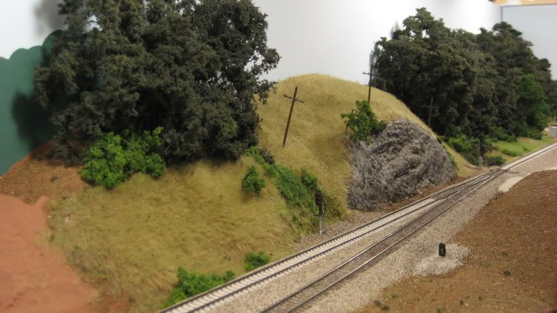
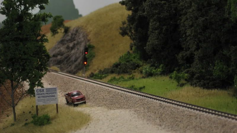
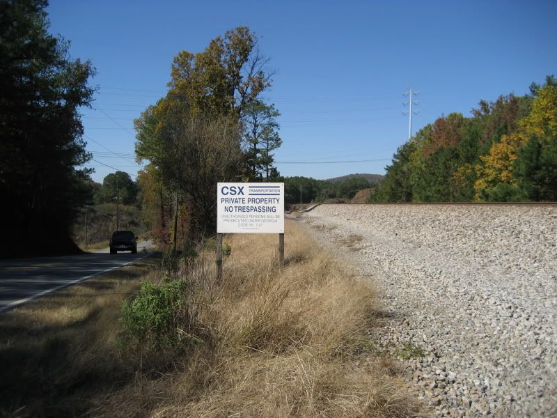

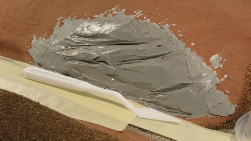
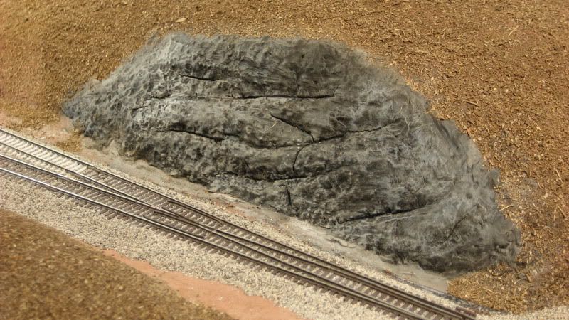
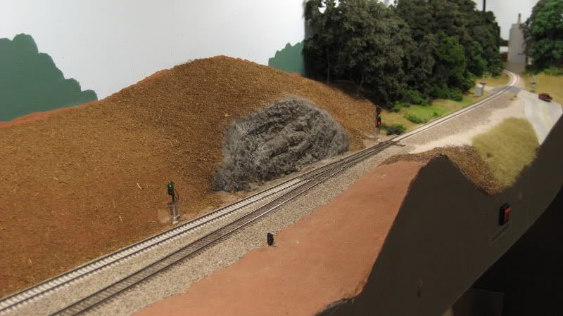
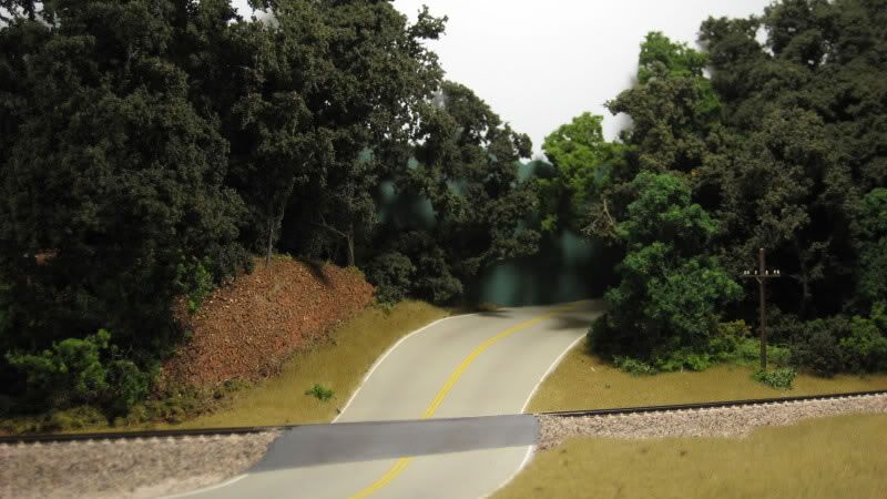
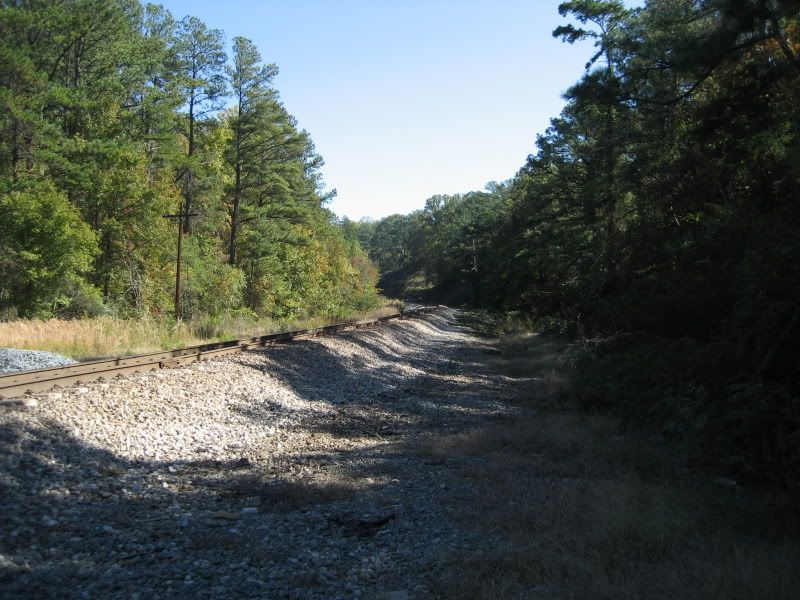
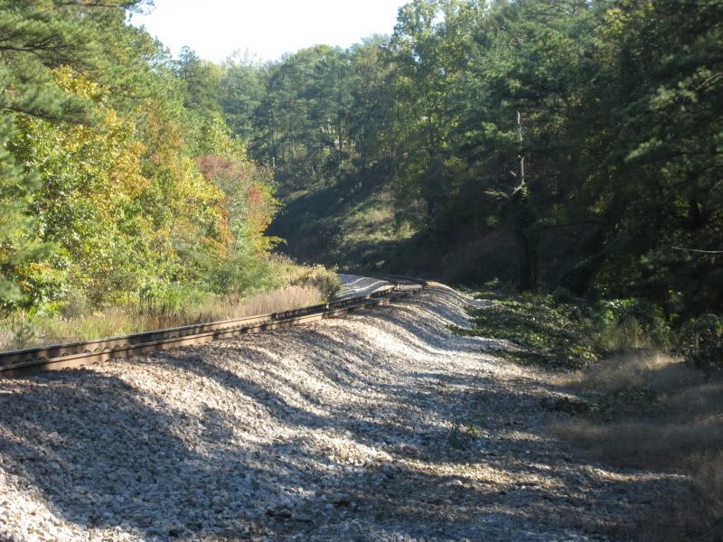
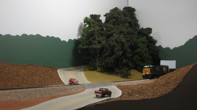
 At the south switch of the Emerson passing siding, the CSX mainline follows the side of a hill that includes a small rock cut that was carved many years ago in order to make room for the roadbed. Staying true to the prototype, I decided to model this rock cut. When I was shaping the basic terrain in this area, I allowed a bit of extra clearance to allow room for the rock cut. I initially planned on using plaster rocks cast in rubber molds, but could not find anything that was an appropriate fit. I then turned to one of Joe Fugate's scenery DVDs which includes a chapter on hand carving rocks. This video series has proved invaluable to me as I have created the layout, and the chapter on hand carved rocks was no different. I have never before done any kind of hand carved plaster work, but armed with the knowledge gleamed from the DVD, I decided to give it a try. The steps below show how I created my very first hand carved rock.