Monday, June 30, 2008

The Train Room

The N-scale CSX Dixie Line layout will occupy a basement room that is 18’-2” long by 9’-2” wide, or roughly 162 square feet in area. This room, which has no windows and a single 36” wide opening (with no door) along one of the long walls, was finished along with most of the basement in the spring of 2002. The floor is covered with padded, commercial grade carpeting and the ceiling features a 2’ x 2’ suspended ceiling grid hung at 9’ above floor level. There are three commercial grade 2’ x 4’ fluorescent lighting fixtures recessed into the ceiling and abundant electrical outlets. This room is wired on an independent 15 amp branch circuit. The entire basement is climate controlled with regards to heating & air conditioning and humidity.

There is really only one hard political constraint with regards to the layout: it must fit entirely in this single room. This includes all mainline, branchline and staging areas. While future expansion may reach into adjoining rooms, I have decided that setting the political boundary to the confines of this single room is the best way to get started and will discourage me from biting off more than I can chew (as if I haven't done this already!). This also means that there will be no carpentry involved with the room itself other than attaching benchwork to the walls as needed. Most importantly, none of my beautiful drywall will need to be punched through!

Photos

Here is a diagram of the room that will house the CSX Dixie Line layout (click any picture for larger version):


Here is a view looking away from the entrance. The helix will be in the distance at the end of the peninsula that runs down the middle of the long axis of the room:


Here is a view looking back the other way towards the entrance. The peninsula will attach to the middle of the short wall, or just behind where my current test layout is:


Here is my current test layout and a small 2' x 4' layout:


The test layout is built on a hollow core interior door mounted on folding banquet table legs. I believe it uses the same track plan that Dave Vollmer's N Scale Pennsy Middle Division layout is based on. I hope to have just a bit of the same success that Dave has had with his impressive layout!


.

Saturday, June 28, 2008

Construction Log

This page includes links to all of the individual construction progress report posts for the CSX Dixie Line layout:

» 2012


» 2011


» 2010


» 2009


» 2008


.

Friday, June 27, 2008

Layout Progress as of 6/27/2008

The first official benchwork materials for the CSX Dixie Line were purchased from The Home Depot in Lilburn, Georgia on Friday 6/27/2008. Although nothing yet has been assembled, I consider this a significant milestone that represents the first tangible evidence of a layout after 15 years of dreaming and about a year of serious planning.

The lumber shown below is two 15-piece bundles of 1" x 2" x 8' that were acquired for $0.69 a piece or about $21.00 total. The benchwork for all of the shelves and the peninsula--basically everything except the helix--will be constructed with this material.


The first lumber purchase for the CSX Dixie Line benchwork is sitting in the corner under the areas labelled Scene "B" and Scene "G" on version 1.0 of the track plan.

Monday, June 23, 2008

Track Plan

>» Track Plan at a Glance


Name: CSX Dixie Line
Scale: N (1:160)
Size: 18'-2" x 9'-2"
Prototype: CSX
Locale: Atlanta to Nashville via Chattanooga
Era: Modern
Style: Multi-deck, around the walls with peninsula
Mainline run: 132 feet (visible)
Minimum radius: 15"
Minimum turnout: no. 10 on mainline, no. 5 branch & staging
Maximum grade: 2.7 percent in helix

» Lower Level


» Upper Level


» Staging Level


.

Sunday, June 22, 2008

Track Plan v1.0

The track plan for the N-scale CSX Dixie Line layout is shown in the diagrams below. It should be noted that this is merely the first version of the track plan and as with all model railroads, many revisions and variations can be expected over time. Also, I have only roughed in the general path of the mainline--there are no sidings, spurs or branches on the plan at this time. In general I plan to have two usable passing sidings on each level to accommodate operational requirements such as meets and helper service.

You will also notice that there are no specific towns or stations on the track plan at this time. Instead, I have roughed in several locations for "scenes" which will eventually be replaced by towns, stations and industries once I have settled on the specific section of the prototype I will model. As it is, I have placed five potential scenes on each level along the straightaways. This provides for 10 individual scenes, which have been labelled using the letters "A" through "J." If you follow a southbound train out of the north staging yard, you will traverse the layout in alphabetical order starting with scene "A" and ending with scene "J" before ending up in the south staging yard. As the plan evolves, I will begin replacing these lettered scenes with the names of the actual locations to be modeled.

Track Plan at a Glance

Name: CSX Dixie Line
Scale: N (1:160)
Size: 18'-2" x 9'-2"
Prototype: CSX from Atlanta to Nashville via Chattanooga
Period: Modern
Style: Multi-deck, around the walls with peninsula
Mainline run: 132 feet (not including staging or helix)
Minimum radius: 15"
Minimum turnout: no. 10 on mainline, no. 5 branch & staging
Maximum grade: 2.7 percent in helix

Pros

  • Layout fits into one room This satisfies the primary political restriction imposed on the layout. Negotiations for right-of-way into other rooms can be deferred until necessary.
  • Long length of mainline run Despite the single room restriction, the multiple deck design allows for 132 feet of mainline track, or roughly four scale miles (two miles per deck). This comes out to about 66 feet of track per deck and when you factor in a maximum train length of around 10 feet, it means each deck can have about six blocks. This will allow room for two passing sidings plus four other blocks, with a goal of having two blocks between the passing sidings.
  • Plenty of staging There are two staging yards on the upper deck of the layout (north and south) that represent the unseen points beyond the "end" of the visible track. Both staging yards have six double ended tracks that have enough length to hold the longest trains that will run on the layout. In fact, the longest tracks have the ability to hold more than one train to allow for serialized staging if desired. There is also ample space to lengthen one of the staging yards as needed.
  • Hidden staging above the layout I originally had this feature in the "cons" section below, but upon further review I have decided this is most definitely a "pro." By placing the staging on top of the layout, I feel I am taking advantage of the fact that this space is readily available on top of the valance for the middle deck and also that a simple extension of the helix allows this space to be reached fairly easily. I plan on having the staging yard "accessible" via the use video cameras and monitors, although time will tell if this feature actually comes to fruition or is simply pie in the sky. In lieu of cameras and monitors, the old reliable combination of mirrors and step ladders should do just fine in providing access to the staging yards.
  • Directional continuity On this track plan north is always to the left and south is always to the right no matter which part of the layout is being viewed. This means engineers following their trains will not be confronted with confusing reversals of direction along their route.
  • Continuous running A northbound train exiting the layout on the north end will eventually re-enter the layout on the south end, and vice-versa for northbound trains. I believe this is a very important feature when planning a layout that could be operated by a single operator, since you can put one (or more depending on how lucky you feel!) trains into motion in one direction and let them orbit the layout while the operator runs his train in the opposite direction and tries to keep out of the path of the oncoming traffic. This will also be a useful feature when showing the layout to others.
  • Build in phases Another important feature of the multi-deck arrangement is that the layout can be built in phases, allowing me to build as little or as much layout as time and resources allow. For example, the first phase to be built will be the lower level. When this is done, only a small portion of the helix will need to be built to function as a return loop at the end of the peninsula. I can then move on to the middle deck and eventually the top staging deck, expanding the helix as necessary as I go.

Cons

  • The insatiable appetite of the helix Each turn of the helix gains 2.5 inches of elevation and takes about eight feet of track. There are 6 turns of the helix between the lower and middle decks and 4 turns between the middle and upper decks. This means that a train traversing the entire helix from the lower deck to the upper (staging) deck will require 10 turns, which is about 80 feet of track, which is about 2 1/2 scale miles! However, I feel this part of the design is a necessary evil and is a acceptable trade off for many of the advantages that this track plan offers. Additionally, there are several well known layouts that successfully employ a similar helix strategy. By placing the helix at the end of the peninsula, I have also provided ready access to the helix from outside or inside. The helix will be hidden from view by use of either a curtain or a removable hardboard fascia.
  • Narrow aisles The track plan as designed uses a standard aisle width of 30", which is about 6 inches narrower than what is preferred. However, since the layout is planned for only one or two operators, this should not pose much of a problem. It is also the widest aisles I could accommodate while still allowing for the peninsula in the middle of the room. Controls will be minimized along the layout fascia to reduce the risk of operators getting snagged on switches and indicators.
  • Long, straight scenes While this may be preferred for Midwest Granger layouts, it is going to be tricky to represent a twisting route through the Appalachians on a shelf that in some places is one foot wide by 18 feet long! However, I believe I can mitigate this by keeping straight track to a minimum and using abundant view blocks to trick the eye into not seeing a straight line. I also plan to keep as much curved track out in the open while any hidden track (such as in tunnels) is on tangent sections.


Sunday, June 1, 2008

Links

» Inspirational Layouts

The following layouts have been instrumental in allowing me to realize my vision for the CSX Dixie Line. I am truly thankful that the builders of these miniature empires have shared their ideas and techniques to allow others such as myself to realize our own dreams.

Joe Fugate's HO Scale Siskiyou Line
I purchased one of Joe Fugate's DVDs in 2007 at a model railroad show, and more than any other single event, this started me on my way to finally designing and building a real layout--my CSX Dixie Line. This DVD was both inspirational and educational. Inspirational: Joe's layout layout captures the look and feel of the real thing so well that there are times when you are not sure if you are looking at pictures of the layout or historical photos of the real Southern Pacific as it winds it way from central Oregon through the Siskiyou Mountains to the Pacific coast. Educational: The research, construction and scenery techniques displayed on the DVD series are presented so clearly and with such simplicity, it really promoted the confidence boost I needed to embark on my layout venture. I consider Joe's layout and his DVD series to be a fountain of model railroading knowledge that I rely upon to realize my vision.

CSXT Shenandoah Division
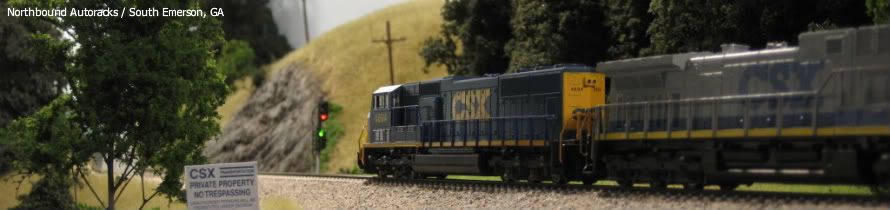
I came across Bruce Faulkner's layout in 2007 while researching the web for ideas on construction techniques that I could use. Not only is the CSXT Shenandoah Division a superb proto-freelanced N-scale empire, but the website detailing the design and construction that began in 2002 is simply off the charts! This railroad shaped my own design in many ways, such as long narrow shelves, long mainline runs, prototypical modern operations, and--most importantly--simple around-the-walls benchwork construction using ripped plywood framing members. You will notice that I have employed very similar benchwork construction in my layout, adapted as needed to fit my available space. Quite simply, I could not have built this benchwork without first seeing how it came together on the CSXT Shenandoah Division. The layout website is also expertly designed and contains a wealth of information that I have relied upon (and still do!) to bring my own layout to reality.

Southern Pacific Coast Line in N Scale
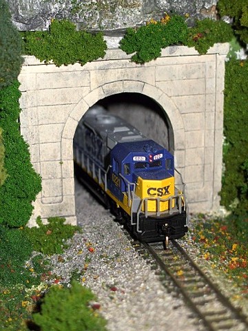
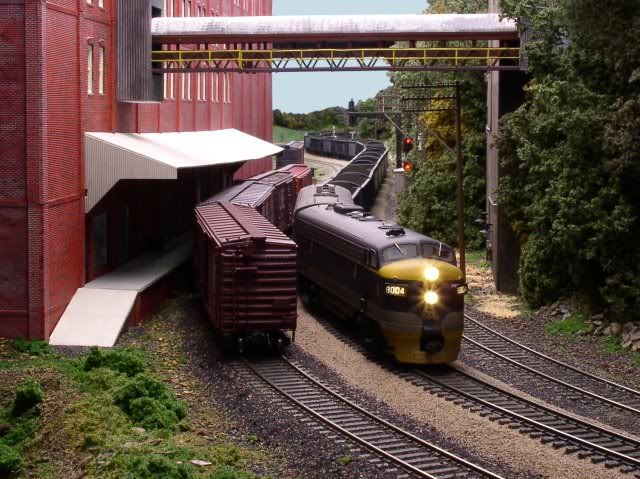
A model railroad layout in N scale (1:160 proportion) representing a portion of the Southern Pacific Coast Line in Central California between Callender and Surf, including Guadalupe yard, set in the early 1970s. The layout is focused on realistic operations and features a great scenery-to-train ratio.

SPSF Owens Valley Subdivision
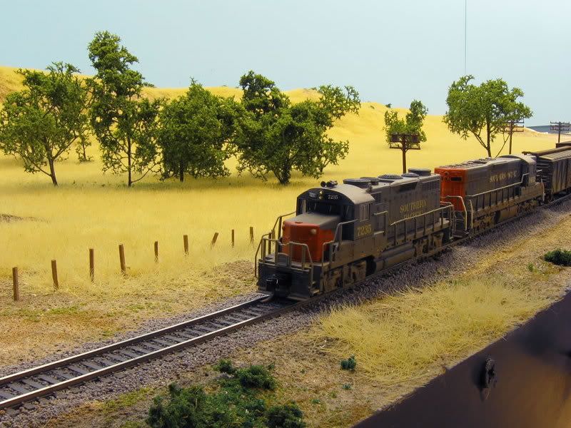
The Owens Valley Subdivision is a double deck N scale layout depicting what could have happened if the merger between the Southern Pacific Railroad and the Santa Fe Railway was approved. It also is a "proto free lanced" railroad, where the prototype never had a standard gauge railroad.

Daryl Kruse's N-Scale UPRR Geneva Subdivision
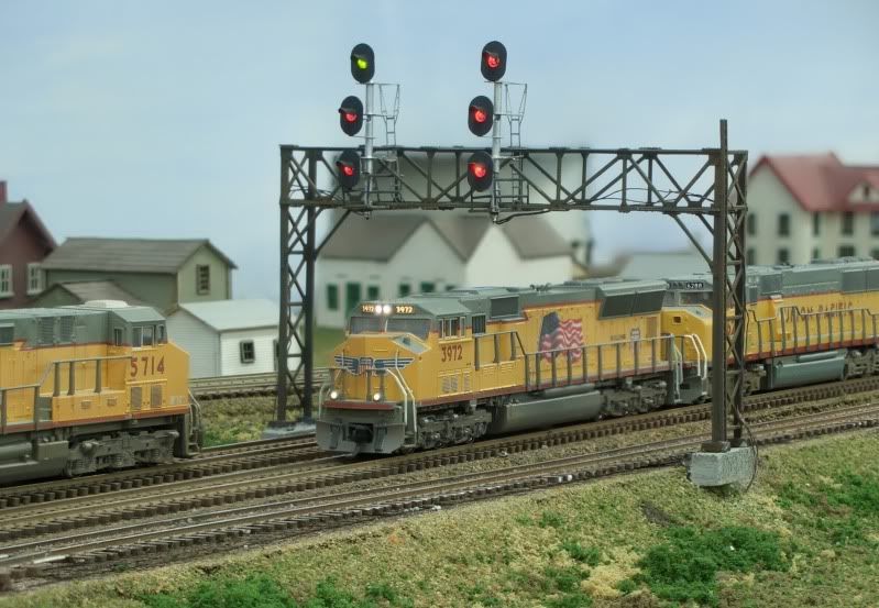
Daryl Kruse models the modern Union Pacific through the nation's heartland. His previous Rochelle Subdivision layout was featured in Model Railroader in 2007 before it was deconstructed to make way for this new empire, which features a long double-track mainline run.

Michael Burgett's HO-Scale Clifton Forge Division of the C&O
This layout takes visitors back to the busy C&O mainline along the James River in Virginia during the mid 1960s. It features prototypical operations, great scenery, a linear track plan on multiple decks, and an incredible operating signal system with a working CTC machine.

John Parker's HO-Scale BNSF Fall River Division
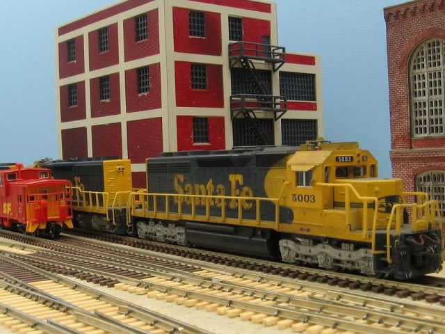
The Fall River Division is a prototype-based freelance representation of the BNSF Railway operating between the Midwest, and points north through the Pacific Northwest. The time frame is between 2000 and 2005, and unit coal, intermodal, Amtrak, and mixed freight trains are frequently seen.

» Forums & Discussion Groups

TrainBoard
Great collection of model railroading and railfanning forums, including the best N-scale model railroading forum on the planet. The information exchanged on this forum, such as how-to, examples and layout tours, has helped me out every time I have got into a jam on my layout. Also an excellent source for model railroad and prototype photography.

» Search Engines & Directories

Model Railroads.Net


RailServe.com: Railroad Travel, Hobby & Industry


.