Saturday, February 21, 2009

Layout Progress as of 2/21/2009

In the last two posts I described how I mocked up the track arrangement in the Emerson area of the CSX Dixie Line layout by temporarily laying the track on sheets of 3/4" blue foam. The track was held in place with pins so it could be moved around to find the ideal arrangement. However, once I settled on a track arrangement, I needed a way to transfer the track centerlines to the benchwork below the foam. I thought about just tapping some finishing nails through the foam to make holes in the tops of the bracket arms, but I also wanted to make sure I could somehow capture the entire mockup in case I needed to refer back to it later when actually laying track.

To do this, I purchased a 75' long roll of 24" wide art paper and cut two 12" wide strips long enough to cover the track mockups. The benchwork is only 11" deep on this part of the layout, so the 12" width of the paper worked out great. I then pinned down the paper and made a few registration marks on the paper and backdrop so I would later know where to place the paper in relation to the benchwork. Finally, I used a black crayon to make a full size tracing of the trackwork. I then removed the foam, pinned the paper directly to the top of the benchwork (using the registration marks as guides) and marked the track centerlines on the bracket arms. These marks will be used to locate the risers for the laminated spline roadbed that will support the track.

Photos

The Emerson area with the completed track mockups on a layer of blue foam:


A long sheet of art paper has been pinned down over the South End Emerson area:


I used a pencil to make registration marks on the paper and backdrop:


I used a crayon to trace the track layout:


I marked the location of turnouts:


I repeated the process for the North End Emerson area:


Next I removed the paper, track and foam, revealing the bare benchwork:


I then used push pins to secure the paper track plan to the benchwork:


I tapped a finishing nail into the top of a bracket arm along the track centerline:


I peeled the paper back and used the crayon to make a distinguishing mark on the bracket arm across the nail hole:


The track centers have been marked on top of all of the bracket arms in the south and north Emerson areas:


.

Wednesday, February 18, 2009

Layout Progress as of 2/18/2009

This week I completed the track arrangements in the Emerson area of the layout. In the previous post, I described how I came up with the final track arrangements along the south end of the Emerson passing siding. This post shows the track arrangements along the north end of the Emerson passing siding, which is where the actual town of Emerson is located. All of these new track arrangements are represented on the latest version of the CSX Dixie Line track plan.

North End Emerson

As with the South End Emerson area, I used a single layer of 3/4" blue foam over the top of the benchwork to use as a sandbox for experimenting with various track arrangements. I used two 8 foot long lengths of 1" wide strips of 1/8" thick Masonite to form a long spline that I used to locate the mainline in Emerson.

This photo shows the spline placed where the mainline will be located through Emerson, with the siding in the middle (with the train on it in the distance) and the house track to the right:


This was actually the first experiment I tried while attempting to find the best location for the house track turnout. Thanks to great feedback from the N-scale community at TrainBoard, I ended up moving the turnout farther back so it would fall along the straight section in the middle of the S-curve in the distance:


This is the same area looking in the other direction (north). You can see the turnout for the north end of the Emerson passing siding in the distance just before the track crosses the gate across the entrance to the train room:


Here is a great example of the benefit of doing these track mockups on foam. The track is held in place using T-pins, so it is very easy to move things around and try different arrangements. I was not happy with the location of the turnout at the north end of the Emerson passing siding so I moved it farther south towards the actual town. Here is a look at the relocated turnout (the house track has been removed to keep things simple):


In the above photo, there will be a street crossing the tracks at grade halfway between the turnout and the row of houses, or right about where the seam is between the two pieces of blue foam. Here is a prototype photo that I took while standing on this grade crossing looking north towards the turnout:


I think the reworked track arrangement does a good job of matching this prototype scene. Here is another view of the reworked track looking south, with a coal train sitting on the siding strung out under the US 41 overpass:


And finally a prototype photo taken from about the same location as the previous layout photo. Notice the tracks pass through a cut where the overpass crosses over:


.

Sunday, February 15, 2009

Layout Progress as of 2/15/2009

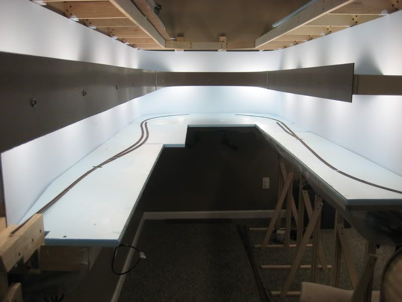
15 days until my first post in February? Too many hours at the office! Over the last week or so I decided to put some sheets of foam down in the Emerson, GA area of the layout to experiment with some track arrangements. This is the southern most point on the layout and will be the first area where track will actually be laid. I got this idea when I found several sheets of 3/4" blue foam hanging out in the furnace room of the basement. These sheets were purchased over 10 years ago for a hollow core door layout that never came to fruition.

I cut the sheets of foam so that all of the layout shelves would be covered plus a good bit of overhang into the aisles in the event I need to increase the depth of a particular scene. With 30" wide aisles, I can afford to eat up a little bit of aisle space at the end of an aisle if I need to.

South End Emerson

The first section of track laid out is the area along the south end of the Emerson passing siding. I started the track mockups at the helix, which is at the end of the peninsula. Upon exiting the helix at the lower level, the inner track goes to the Emerson scene and the outer track goes to the Cartersville scene. I placed the location of the helix-to-Emerson track centerline using a section of Masonite spline that will eventually be used for the actual spline roadbed:


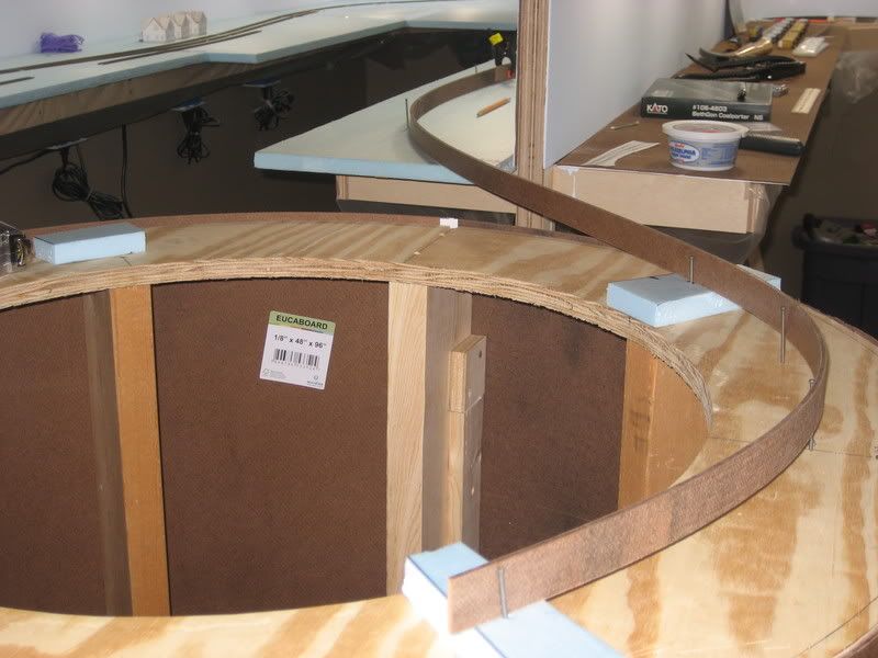
Let me take a second to explain the above photo. In the foreground is the 36" diameter helix base. The inner track of the helix will have a 15" radius--the end of the spline closest to the camera (bottom center) is aligned where this track will be located and follows its path about 1/4 turn counterclockwise where it exits the helix atop the other small block of blue foam (middle right of the photo). The track/spline then exits the helix and enters the Emerson side of the peninsula, bending out of site behind the double sided backdrop that runs down the middle of the peninsula. The Cartersville side of the peninsula is to the right where all the junk has accumulated. The small blocks of blue foam are to make sure that the spline is at the same height on the helix and the rest of the layout.

My goal for these track mockups is to produce a full size trackplan on the blue foam. I will then need to figure out some way to transfer this plan to the tops of the benchwork after I remove the sheets of foam so I can reproduce the track arrangements using Masonite spline roadbed. In other words, the foam is my sandbox where I can play around with different track arrangements until I find the most ideal solution (with regards to both looks and operational possibilities).

To "place track" on the blue foam, I used some 8' long scraps of 1" wide strips of 1/8" Masonite left over from the backdrops and fascia to form some splines. These splines work great because they are sturdy but flexible and form nice flowing curves with natural easements when bent. I clamped two of these splines together using cheap 1" spring clamps so I could have a nice long strip to work with. I held the spline in place using 6d finishing nails pushed into the soft foam using my fingers. If the placement did not look good, it was easy enough to pull out the nails and try a different arrangement.

This photo shows the long spline used to locate where the mainline will be placed in the South End Emerson area of the layout:


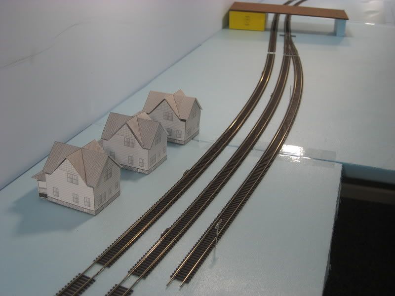
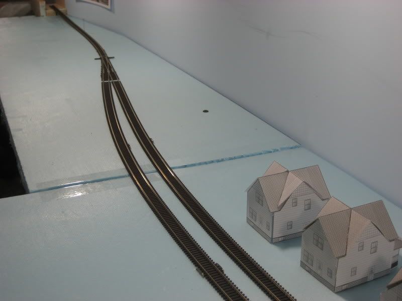
A closer look at the same area from the previous photo. I have assembled a #10 LH turnout and a couple of sections of flextrack to get an idea of where the Emerson siding will be located (all track used in these mockups is Atlas code 55):


When satisfied with the track arrangement, I used a Sharpie marker to place marks on the foam where the track centerline was located by the spline. I then removed the spline and assembled actual pieces of track to make sure the "real thing" looked as good as the spline placement:


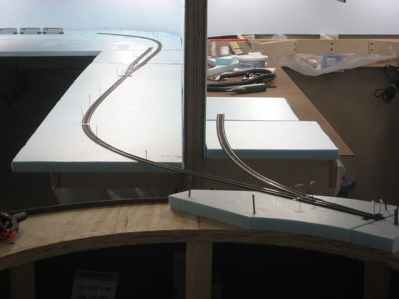
The previous photo shows the same location as the first photo of this post. The spline has been removed, an extra piece of foam has been added for support, and actual track has been placed to check alignments. The track is attached to the foam using cheap T-pins that make it very easy to shift track around as needed to find the ideal fit.

In the above photo you can see that the inner track of the helix actually splits via a #7 RH turnout, with the through route going to the Emerson side of the peninsula (to the left) and the diverging route going to the Cartersville side (to the right). This latter route will merge with the outer track of the helix in Cartersville at a junction, making this short piece of track a reversing loop that will greatly enhance operational flexibility. This new track arrangement is now shown on the most recent version of the track plan.

This #7 turnout is in a tricky location with regards to the helix. To mitigate this, a return loop will be built in place of the helix until upper deck construction begins far down the road...months? years? ever? This insures lots of trains will run through this turnout over a long period of time, allowing any bugs to be ironed out well before the helix is ever built.

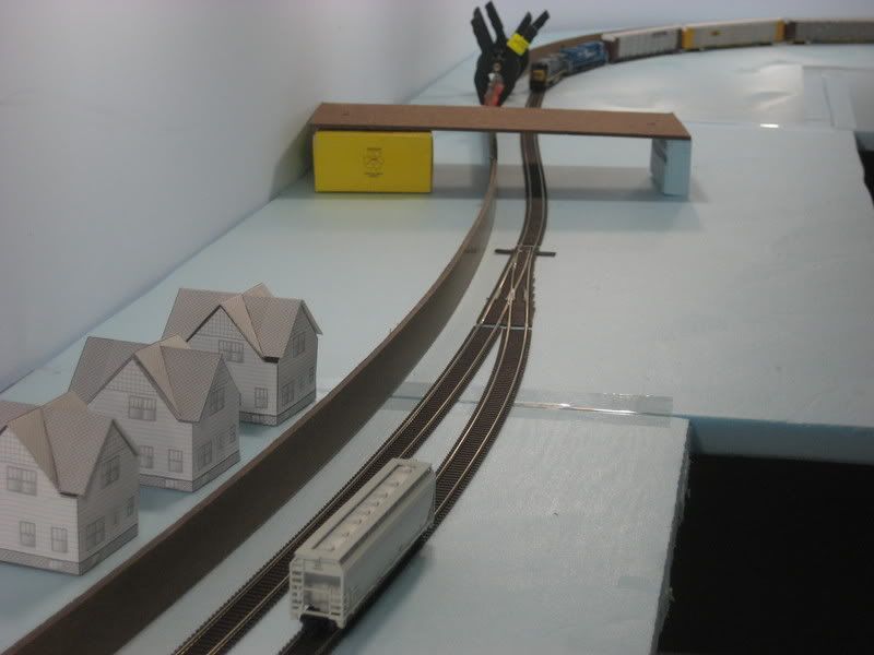
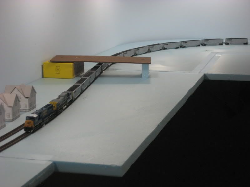
A wider view of the same area with the temporary track in place:


A closer look at the south end of the Emerson passing siding. The siding will actually begin about 12" closer to the camera, but I did not want to cut any flextrack just to place temporary track:


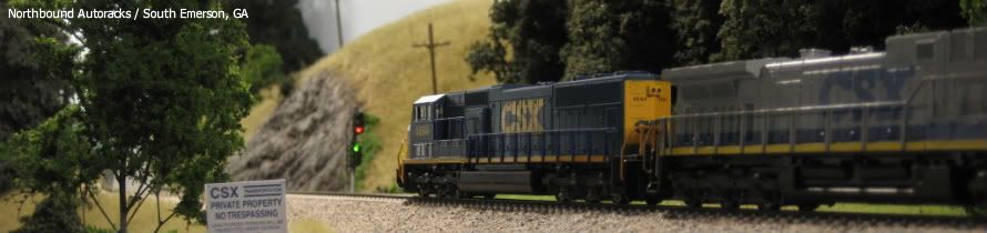
Finally, just to put things into perspective, two prototype photos showing what will be modeled on the South End Emerson area of the layout. The first photo is a panorama that looks at the extreme south section of the visible portion of the layout. Using your imagination, try to picture that #7 turnout at the end of the helix just out of sight to the right of this photo and the south end of the passing siding just out of view to the left:


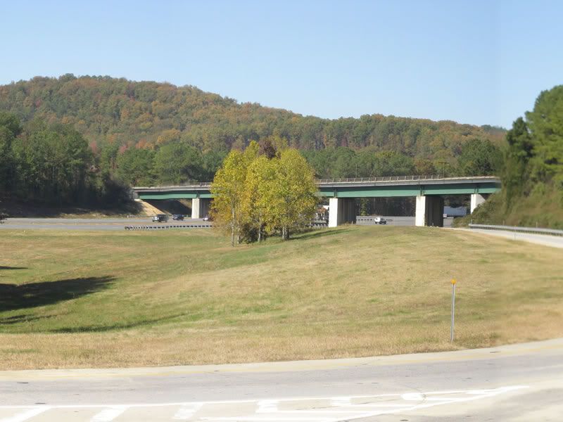
This photo shows where the two tracks cross I-75. In the layout photo above, this bridge will be placed between the turnout for the south end of the passing siding and the far end of the peninsula where the tracks begin the 180 degree horseshoe curve around the end of the aisle:


.

Saturday, February 14, 2009

Track Plan v3.0

There a few significant changes in version 3.0 of the CSX Dixie Line track plan:

(1) The helix has reverted back to a circle from the oval that appeared in the previous version of the track plan. I have become convinced that the circular helix will perform just fine based on feedback I have received from owners of other layouts. I can always go back to the oval (apace is available) in the event the circular helix experiences problems.

(2) The K&A Subdivision track has been added between the helix and the Cartersville area. This track will serve as a reverse loop section and greatly enhance operations. Trains running between Atlanta, GA and Knoxvile, TN 9and points north) will now enter and exit the layout on this track. The will basically go from south staging-to-staging while only appearing on the lower level of the layout, which is prototypically correct.

(3) The Emerson area of the trackplan now shows track arrangements as they will actually appear on the layout. This arrangement was laid out using actual track mockups on the layout.

Lower Level


Middle Level


Upper Level


.