Saturday, January 31, 2009

Layout Tour

This page shows all of the layout design elements (LDEs) included on the CSX Dixie Line track plan. An LDE is a scene featuring a specific location on a model railroad; multiple LDEs are placed adjacent to each other to create a complete layout. You can click the links below to go to a page describing all of the details of that particular LDE. Take note that all of the LDEs shown on this page are included in the same south-to-north order that they appear on the CSX prototype, one of the main reasons I selected this area to be modeled.

Layout Design Elements

Coming Soon!

.

Thursday, January 29, 2009

Layout Progress as of 1/29/2009

Layout progress has slowed to a crawl as I hunker down at work to finish another major project deadline. Although I would like to have more free time to work on trains, I have to say I am very thankful to be employed given the state of the economy right now. In the little time I have had to work on the layout, I started doing some structure mockups that I will be using when I go to layout the trackplan. I purchased the N-scale Atlas Kim's Classic American Home kit (photo from Atlas website):


I then took measurements from the parts of the kit and drew a template in Microsoft Visio (this template will create two houses):


Click here to download the PDF template

I then printed the template on plain old 8.5" x 11" paper, glued the paper to poster board using 3M spray adhesive, cut out the pieces and assembled them by locking the tabs together and securing with tape. I then placed a few of the houses on the layout in the town of Emerson, GA with a few other "props" to see how things will fit together:


And finally, to have a bit of fun I digitally inserted a background from the actual Emerson area to give a better idea of how a finished scene would look:


After reading a few articles in Model Railroader highlighting the use of photo backdrops and playing around with them in digital images, I am really starting to lean in that direction. Next I plan on making some mockups of actual structures in Emerson so I can begin to layout the actual town scene.

.

Sunday, January 18, 2009

Layout Progress as of 1/18/2009

Over the weekend I completed two projects for the N-scale CSX Dixie Line. First, I completed the dropdown gate that crosses the doorway to the layout room on the lower level of the layout. I have included a detailed step-by-step account of how I built this gate in a separate HOWTO article. Here is a picture of the completed gate and a video showing the gate in action:


Finally, I overpainted a section of the backdrop with a solid light sky blue color:


This section of the backdrop had previously been painted with two shades of blue to simulate the lighter sky color at the horizon, but I subsequently decided I liked the solid light blue much better. I may try airbrushing white on the lower half of the backdrop to simulate the horizon, but that will be another project for another day.

.

Friday, January 16, 2009

DIY: Install a Dropdown Gate

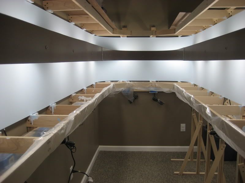
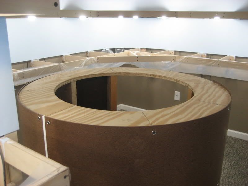
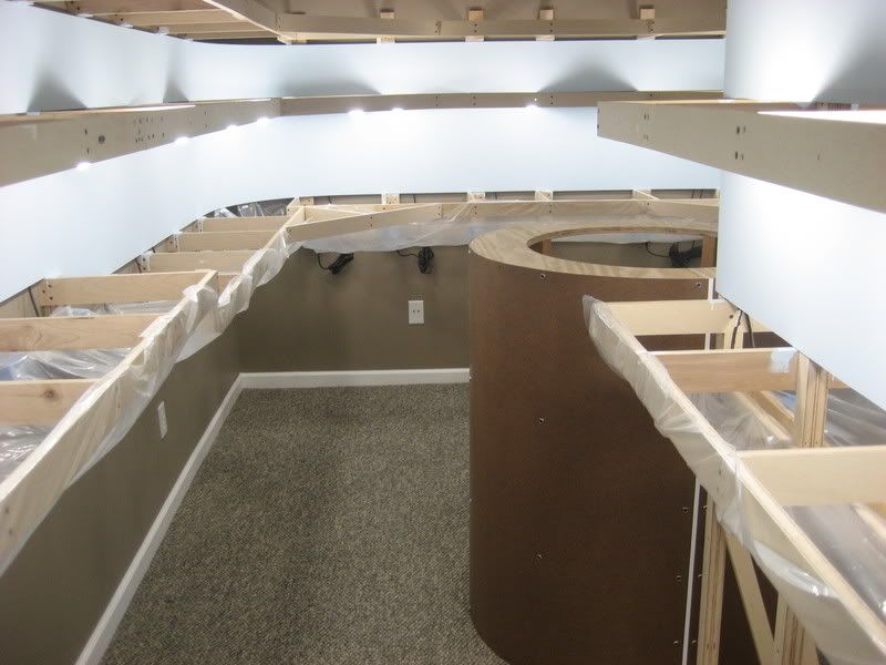
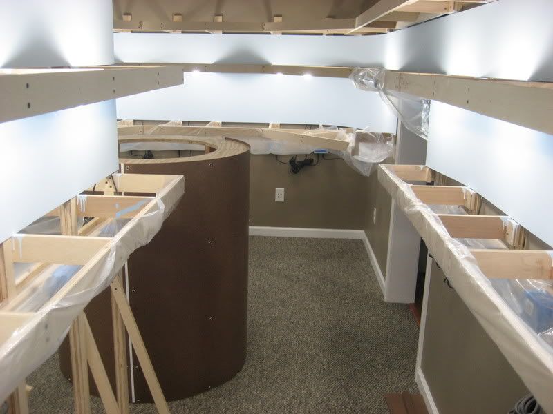
This post takes a highly detailed step-by-step look at how I built the dropdown gate across the doorway on the lower level of my N-Scale CSX Dixie Line layout. The gate will provide two functions: 1) allow trains to get from one side of the doorway to the other and 2) allow people to enter and exit the layout room easily. While the upper level can be ducked under fairly easily, asking a person to duck under the lower level would just be too much to ask!

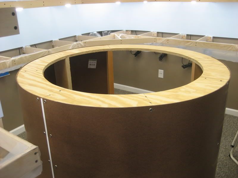
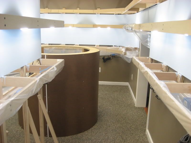
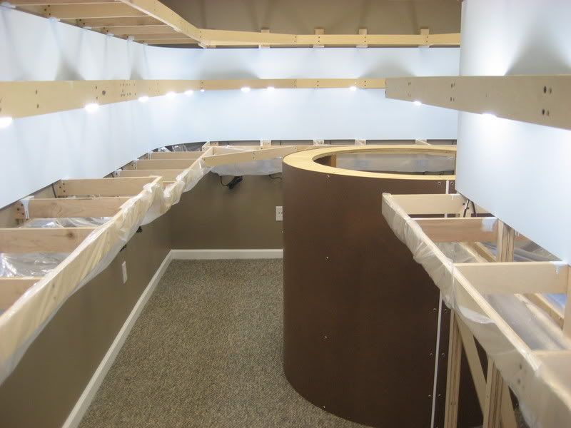
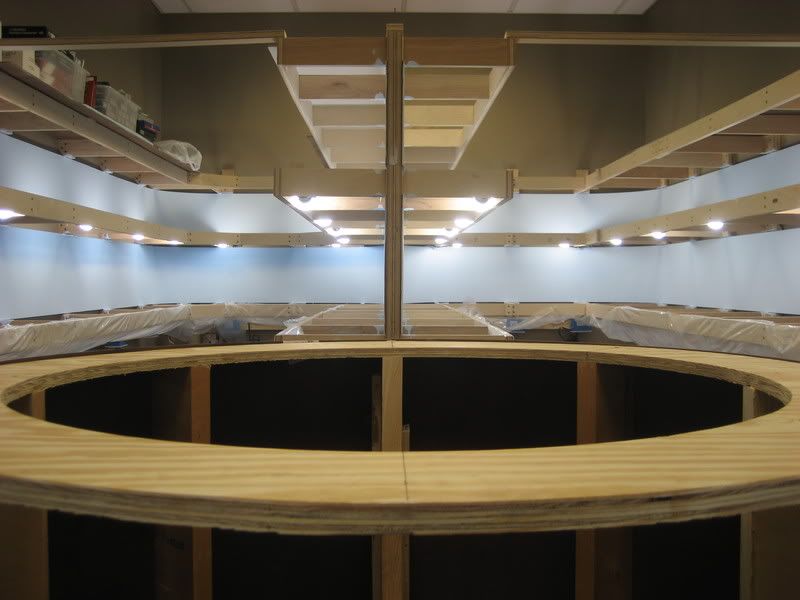
Step 1 Looking back at an earlier picture of the layout, you can see where the gate will go. The distance across the doorway (between the wall bracket arms on either side) is 43.5", so the length of the bridge will be 46.5" to accommodate for the 3/4" width of each wall bracket arm and an additional 3/4" cleat on each bracket arm that the ends of the bridge will rest on:
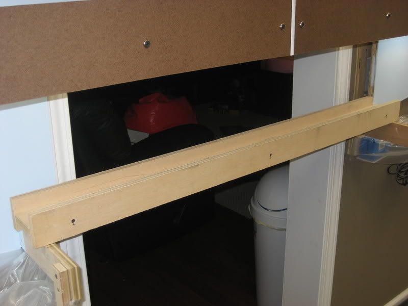


Step 2 The bridge span is constructed of three 1x3" boards ripped from 3/4" birch plywood and cut to a length of 46.5". The three boards are held together temporarily using three drywall screws on each side so the assembly can be test fitted on the layout:
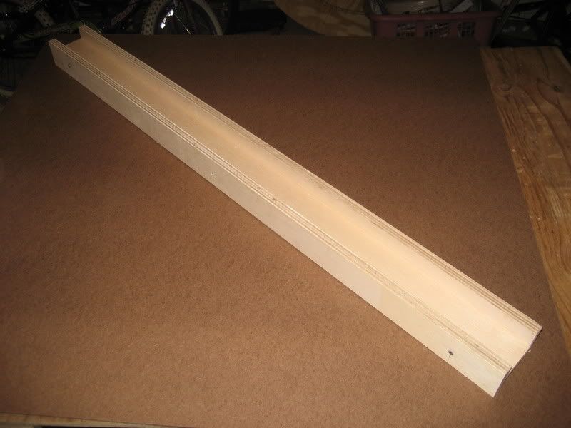


Step 3 A closer look at the end of the bridge span reveals the sideways I-beam arrangement of the three 1x3" boards. There are a few reasons I chose this construction for the bridge span:

1) The horizontal bridge deck will provide a nice wide, level surface for mounting the roadbed and track.
2) The vertical sides will prevent sag of the bridge deck.
3) The vertical sides will act as guard rails to prevent a derailed train from "taking the plunge."
4) When the vertical sides rest on the wall bracket arms, the surface of the bridge deck will be 1.5" above the tops of the wall bracket arms, which is an exact match to the top surface of the spline roadbed that will be used on the lower level of the layout.


Step 4 The backdrop on the right side of the doorway bends forward so the wall switches to the room lights can be accessed. This required the back side of the bridge to be notched so it would fit on the layout as far back from the front of the benchwork as possible. The track in this area runs quite close to the backdrop to accommodate the turnouts for the siding and house track at North End Emerson:


Step 5 The vertical sides of the bridge span rest atop the wall bracket arms on either side of the doorway. However, I had to build some "piers" on both wall bracket arms so there would be a good place to fasten the bridge ends and add support. I built the piers using scraps of the same 1x3" boards used to build the bridge span (this picture shows the left side pier; the right side is identical):


Step 6 
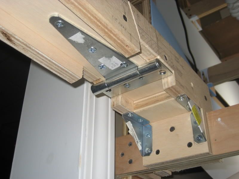
These pictures show how the bridge span sits atop the bridge piers. I have fastened the bridge span to the pier using a pair of 2" angle brackets. The angle brackets hold the bridge span in place and also resist the downward forces on the cantilevered section of the bridge span when the gate is opened (these pictures show the left side pier; the right side is identical):


Step 7 I cut notches in the bottom of each bridge side so that the 4" gate hinge could be attached to the bottom of the bridge span using eight 3/4" #10 wood screws. Note that the square side of the hinge is actually screwed into the bridge deck and the bridge sides. I used a jigsaw to make these cuts, which explains why they are so ragged and the top of the notch does not line up with the bottom of the bridge deck as it should:


Step 8 
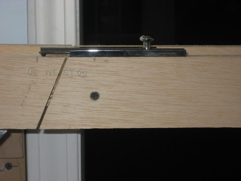
I marked the locations of the diagonal cuts on each board of the bridge span and made the cuts using a chop saw. As I was about to make the cuts, I remembered to mark each board so I would know how the pieces would go back together:


Step 9 
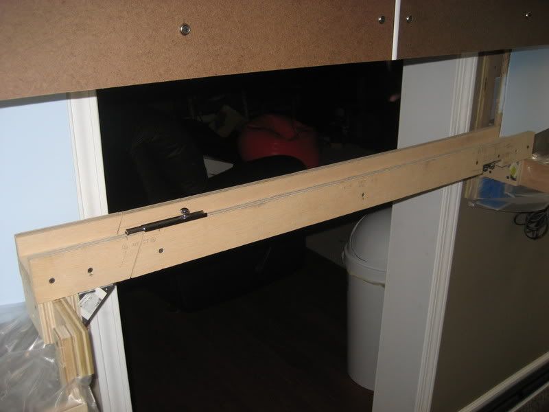
I reassembled the bridge assembly and held my breath as I put it in place...everything fit correctly!


Step 10 I used a sliding door bolt as the locking mechanism on the gate. The next few pictures show how this was installed. Note that the sliding part of the bolt actually rests on top of a drywall screw on the other side of the gap. This is needed to keep the bridge deck at the same height on both sides of the gap. Note how the diagonal cuts in the bridge sides do not line up with the diagonal cut bridge deck--this results in the bridge deck forming a "tongue" that fits between the bridge sides when in the closed position to maintain side-to-side alignment:


Step 11 A second door bolt was required to keep the bridge deck level when the gate is locked closed:


Step 12 I used 4" mending plates strengthen the attachment of the bridge piers to the wall bracket arms:


Step 13 I am using laminated spline sub-roadbed for the layout. After the gate was completed, I realized I failed to notch the ends of the bridge deck so a center spline of the roadbed could be attached to the ends of the bridge. I disassembled the bridge and cut 1/8" notches 1.5" deep into each end of the bridge deck. Since the splines will be 1/8" wide and 3/4" tall, these notches will keep the bridge and the sub-roadbed in perfect alignment:


Completed Gate Finally, a few shots of the completed gate in the open and closed positions:


.

Wednesday, January 14, 2009

Layout Progress as of 1/14/2009

This week I started construction of the dropdown gate that crosses the doorway on the lower level of the N-scale CSX Dixie Line layout. I decided to go with a dropdown style gate rather than a swing in/out or lift-out style because I felt it could be easily built with minimal addition to the existing benchwork. So far, I have only managed to assemble the actual bridge. This is just a temporary assembly, since it will need to be disassembled for cutting and adding the hinge and bolts that will make the entire assembly work. By doing this temporary assembly, I was able to test fit the bridge on the actual layout and determine the best position.

The bridge is constructed out of three 46.5" long 1x3" boards ripped from plywood assembled in a "U" shape. The horizontal board serves as the bridge deck that the roadbed and track will be mounted on, while the vertical boards prevent sagging and warping of the assembly:


A closer look at the basic "U" construction of the bridge assembly. The vertical members also serve as guard rails that will prevent a derailed train from "taking the plunge":


The bridge has been set in place to test the fit onto the layout:


The next steps will be to cutout the movable portion of the bridge, attach the hinge to allow this portion to swing up and down, and attach the door bolts that lock the bridge into the closed position.

.

Sunday, January 11, 2009

Layout Progress as of 1/11/2009

This week I installed the fascia on the front boards between the lower two levels of the CSX Dixie Line layout. Although this could have easily been deferred to a future project, I went ahead and did it now because the glare from the visible layout lighting was really getting to be annoying, especially in photography. It is also much nicer walking around and working in the train room without having to stare directly into 31 lighting fixtures.

The fascia is made of 5" wide strips of 1/8" tempered hardboard fastened to the front boards with drywall screws and finishing washers. I used vinyl paneling molding between all vertical seams to yield a nice, clean look. When completed, the fascia will be primed and painted to match the color of the room walls.

The following two photos show the dramatic improvement from installing the fascia. The two photos show the helix base taken from basically the same angle, but the first was taken before installation of the fascia and the second was taken afterwards. Notice how much more "pleasant" everything looks with the lights blocked out by the fascia:


.

Wednesday, January 7, 2009

Layout Progress as of 1/8/2009

In my previous construction update from Januray 5, 2009, I described how I built the base for the future helix. While I was happy with the way the helix base turned out, something was just bugging me about it. After some thought, I realized it was just too darn big and taking up too much space in the layout room. I noticed this a bit as soon as it was completed, but it became more and more obvious as I reviewed photos of the room with the new helix base in place. Plus, every time I had to turn sideways to squeeze past, I felt like I needed to install one of these signs:


Originally, I planned a 36" diameter helix but switched to 48" at the last moment when I thought the extra size would not make a difference (wrong!) and the added circumference would reduce the grades from about 2.5% to about 1.5%. I have now rebuilt the helix base according to the original plan using the 36" diameter base, which yielded an additional 6" of aisle space on each side. I made this decision based on two tests:

(1) I moved the previous jumbo helix base (48") over six inches and could walk comfortably past it without turning sideways or brushing against it or the benchwork across the aisle.

(2) I broke out some track and rolling stock and determined I can go with a 2" separation between levels of the helix instead of the planned 2.5" separation. This change will result in about a 2.0% grade in the helix, much better than the originally planned 2.5%. With 2" spacing between levels, there will be at least 0.25" of clearance between the tops of my tallest cars and the roadbed above. Not an abundance of space, but should not be a problem because I have full access to both tracks from inside and outside the helix.

I started the rebuild by cutting the new top and bottom rings out of the circles of plywood leftover from cutting the rings for the old larger helix base. Since I could do this, no additional materials needed to be purchased. Plus, as an added bonus, the lines were already drawn across the circles from the previous cuts! All I had to do was mark the inside circle radius and make two cuts (one per circle):


The old inside radius of the large helix base rings was actually 18.5" and the new outside radius of the smaller helix base rings should be 18", but since the difference was minimal, I did not cut off the outer 1/2" of the rings. This saved two long circular cuts with the sabre saw, which was just fine by me! You can see the actual 18" radius drawn near the outside edge of one of the new rings:


Finally, a few different views of the completed helix base. Be sure to take a look at the previous post for a size comparison to the old "jumbo" helix base:


.

Monday, January 5, 2009

Layout Progress as of 1/5/2009

On New Years Day and the following weekend, I framed the base of the double-track helix that will allow trains to move between the three levels of the CSX Dixie Line layout. The helix base was constructed out of a base and top cut from 3/4" A-C grade plywood and seven 2x6" studs. Finally, the outside was sheathed using 1/8" tempered hardboard. Only three fourths of the exterior is sheathed, leaving the remaining one fourth to be used as an access opening to reach the track and wiring from the inside of the helix. Eventually, the helix base will be primed and painted to match the train room wall colors (as will the layout fascia) and a black curtain will be hung across the access opening. The helix itself will be built using 16 3/8" threaded rods attached to the base using tee nuts; the track roadbed will be two layers of laminated 1/8" tempered hardboard. The following photos show how the helix base was constructed.

A template was drawn on two 4x4' sheets of 3/4" A-C grade plywood. The circles that make up the bottom and top rings of the helix base have an outside radius of 48" and an inside radius of 42 1/2". The 5 1/2" width of the rings was chosen to accommodate the actual width of a stick of 2x6" dimensional lumber. The lines radiating out of the center point of the sheet of plywood indicate where the studs will be mounted to the rings:


After the rings have been cutout, the bottom ring is placed where the helix will be located to obtain a test fit:


Next, the first three studs are attached to the bottom ring using angle brackets and screws:


Then the top ring is placed on top of the first three studs and secured using a pair of drywall screws driven down into the studs. The remaining studs are then added to fill in the gaps. The missing stud at the front is actually omitted intentionally to allow access to the inside of the helix:


The outside of the helix base is sheathed using 1/8" tempered hardboard attached with drywall screws and finishing washers:


Here are a few overall views showing how the completed helix base fits into the layout. Although the aisles narrow down to about 20" wide to accommodate the helix, this is still ample aisle width to allow a single operator to easily slip past:


.