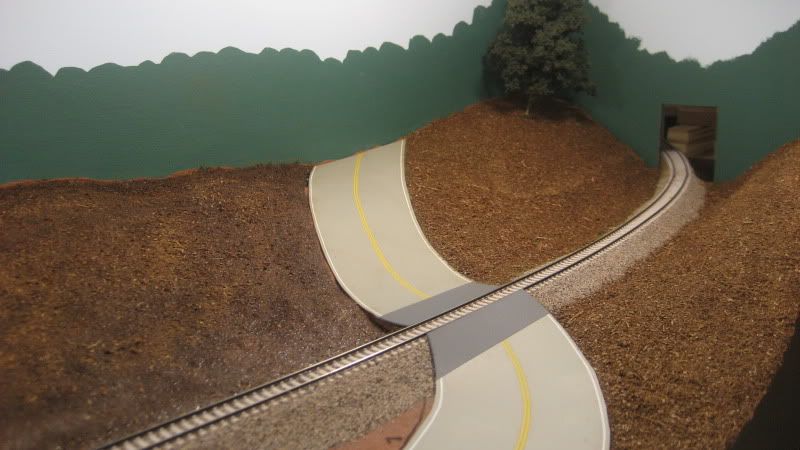
When it comes to static grass, I can think of no other innovation that has contributed more to the realism of model railroad scenery. The texture and depth provided by static grass fibers really make scenes "pop." The only drawback to using static grass is the limited availability of commercial static grass applicators and the high price of the ones that are available. The NOCH GRASSmaster, for example, has a street price above $175. That's a lot of green to spend on making realistic green on your layout. Fortunately, several modelers have published plans for homemade static grass applicators that will only set you back around $30. That's more like it!
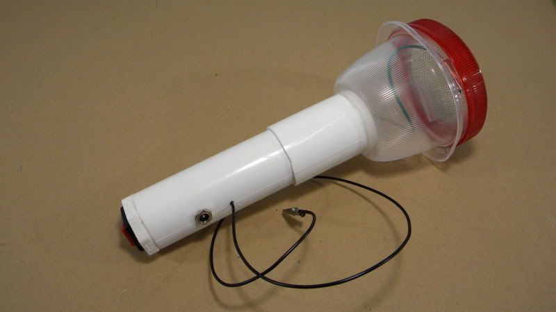
The static grass applicator I built as described in this post is a hybrid of the Ztrains Grassinator and Joe Fugate's own homemade applicator. Of course, as with most hobby projects, I threw in a few of my own variations where I felt certain parts or procedures would work better. The applicator pictured in the photo above shows the results of the steps I have included below.
» Parts List
These are the parts that I used to construct my static grass applicator:
- Enercell™ 12V/500mA AC Adapter (Radio Shack #273-357)
- Enercell™ Adaptaplug™ M (Radio Shack #273-344)
- Size M Panel-mount Coaxial Power Jack (Radio Shack #274-1582)
- SPST Rocker Switch (Red) (Radio Shack #275-694)
- Mini 1-1/4" Alligator Clips (Radio Shack #270-380)
- 75-Ft. UL-Recognized Hookup Wire (20AWG) (Radio Shack #278-1222)
- Negative ion generator (Oatley Electronics #IONB)
- 8" long 1 1/2" diameter PVC sink tailpiece (Ace Hardware #4224218)
- PVC plug that fits the flange end of the tailpiece (Ace Hardware)
- PVC plug that fits the non-flange end of the tailpiece (Ace Hardware)
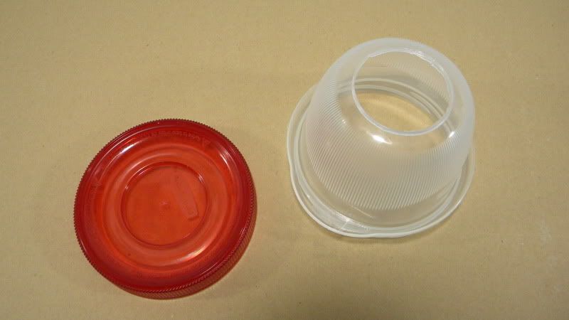
- Rubbermaid TakeAlongs 1.2 cup container (Rubbermaid #7H99)
- Metal window screen (Ace Hardware)
» Steps
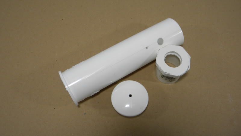
Step 1 To get started, cut 2" off the sink tailpiece to make it 6" long. Be sure to cut from the end of the pipe without the flange, since the flange will be used to secure the grass cup to the pipe in a later step. Do NOT discard the small 2" long piece that you cut off of the tailpiece since this will also be used later on to secure the grass cup to the pipe.
Step 2 Drill two holes in the tailpiece: drill a 21/64" hole 1 1/4" from the end of the pipe, then drill a 1/16" hole 2" from the same end of the pipe. Measure from the cut end (not the flange end) of the tailpiece when drilling these holes. Also, drill these two holes in line with each other; the seam of the tailpiece makes a natural guideline for doing this.
Step 3 Drill a hole in each of the two tailpiece plugs: drill a 3/4" hole in the plug that will cover the cut end of the tailpiece, then drill a 1/8" hole in the plug that will cover the flange end of the tailpiece.
The following photo shows how all of my parts looked after cutting the tailpiece and drilling all of the holes:
Step 4 Using a sharp hobby knife, carefully cut a large hole in the bottom of the Rubbermaid container. The hole should be just large enough so the container will slide down over the cut end of the tailpiece and snug up against the flange end:
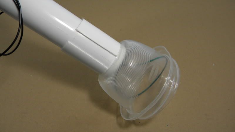
Step 5 Run a bead of super glue along the back side of the tailpiece flange and pull the grass cup snug against the flange to permanently fasten it to the tailpiece:

Step 6 Make a vertical cut through one side of the small 2" long section of tailpiece that was cut off in a previous step. This cut will allow the short piece to expand and slip over the cut end of the tailpiece like a collar. Slide this collar all the way down against the grass cup and super glue it in place. The grass cup will now be permanently locked between the collar and the flange. Disregard the two wires shown here; I attached some of the electronics before I realized I forgot to attach the cup and sleeve:
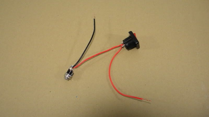
Step 7 Solder a 4" long piece of black hookup wire to the negative (-) pin of the power jack. Solder a 4" long piece of red hookup wire to the positive (+) pin of the power jack. Solder the other end of this red wire to one pin of the toggle switch. Solder another 4" long piece of red hookup wire to the other pin of the toggle switch:
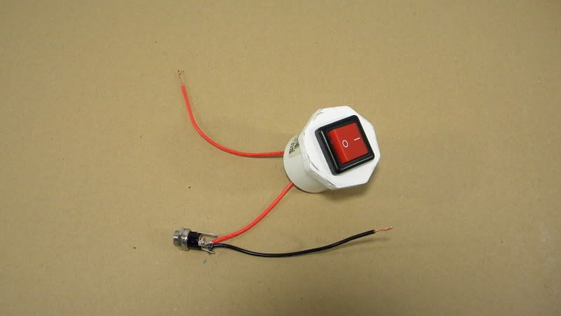
Step 8 Insert the toggle switch into the hole drilled into the plug that will cover the cut end of the tailpiece. Secure the toggle switch using the nut provided:
Step 9 Insert a 2' long piece of black hookup wire through the smaller hole drilled into the tailpiece. Pull the wire through the cut end of the tailpiece:
Step 10 Attach the black hookup wire from the previous step, along with the black hookup wire from the power jack, to the black wire of the ion generator. Use a small wire nut to bundle these three wires together. Using another wire nut, attach the red hookup wire from the rocker switch to the red wire of the ion generator. The white wire of the ion generator with the small brush should not be attached at this time:

Step 11 Cut the small brush off of the white wire of the ion generator and attach it to a 2' long piece of green hookup wire using a small wire nut:

Step 12 Push the ion generator down into the cut end of the tailpiece. The white/green wire should go in first; pull this wire through the flange end of the tailpiece (remember, I forgot to install my grass cup before installing the electronics so the grass cup does not appear yet in my photos):
Step 13 Remove the nut and washer from the power jack. Push the power jack down into the cut end of the tailpiece, then push the threaded end of the jack through the larger of the two holes drilled earlier into the tailpiece. Secure the power jack using the washer and nut:
Step 14 Push the plug with the rocker switch down into the cut end of the tailpiece and secure it with super glue or some other adhesive. Since my plug did not have a very tight fit in the cut end of the tailpiece, I used a bead of LocTite Power Grab construction adhesive to hold it in place (in this photo you can see that I finally remembered to slide the grass cup in place):

Step 15 Insert the other plug (the one with the small 1/8" hole drilled in it) into the flange end of the tailpiece, feeding the green hookup wire through the hole. Secure it with super glue or some other adhesive:
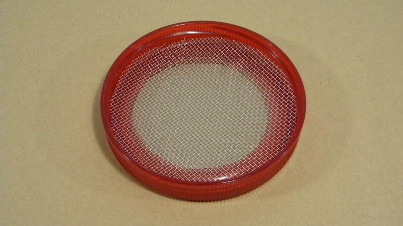
Step 16 Using a sharp hobby knife, carefully cut a large hole in the lid of the Rubbermaid container. Using a pair of scissors or snips, cut a round piece of window screen about the same diameter as the lid of the Rubbermaid container. You want this circle of screen wire to be small enough to fit inside the lid, but large enough so that you can "snap" it in behind the threads of the lid:
Step 17 Drill two small holes through the Rubbermaid container lid and the screen wire. Insert one 4-40 x 3/4" screw into each hole and secure each screw with a 4-40 nut. Solder an alligator clip to the end of the green hookup wire extending through the plug in the flange end of the tailpiece, then clip the green hookup wire to either of the screws:
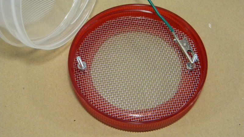
Step 17 Solder an alligator clip to the end of the black hookup wire extending from the small hole in the side of the tailpiece:
Your static grass applicator is now complete!
.