Showing posts with label Construction. Show all posts

Tuesday, January 1, 2013

Building the Etowah River Bridge: Part 1


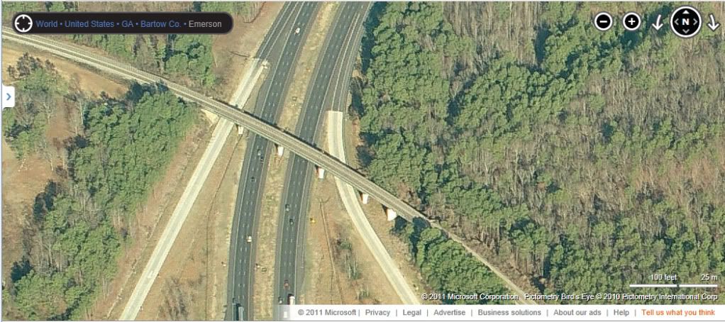
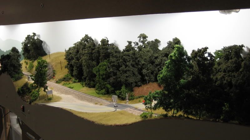
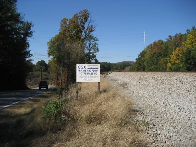
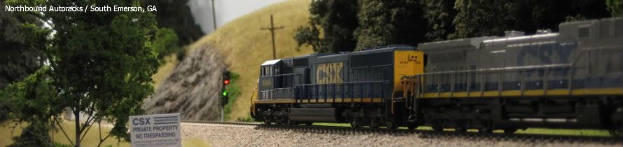
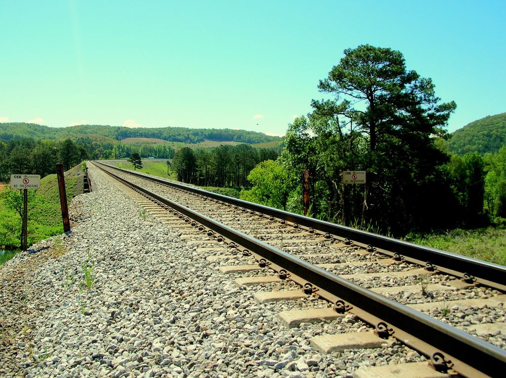
The CSX W&A subdivision crosses the Etowah River in scenic Bartow County, Georgia about 40 miles northeast of downtown Atlanta. This location has great sentimental value to me because it was the first location I railfanned with my family when I was seriously getting into the hobby back in 2007. The photo above was taken by Patrick Phelan (via RailPictures.net, used by permission) and led me to explore the area in the first place. I have it taped to the fascia on the layout to use as motivation for bringing this scene to life.

» The Prototype


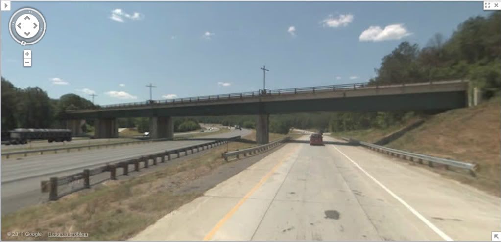
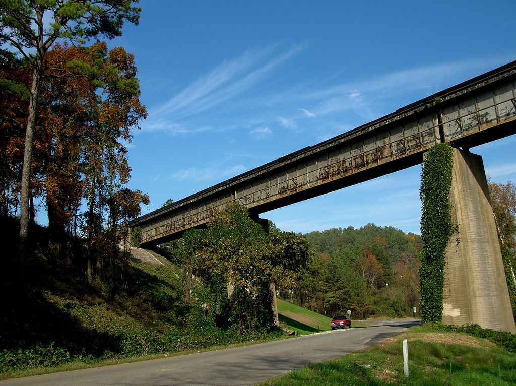
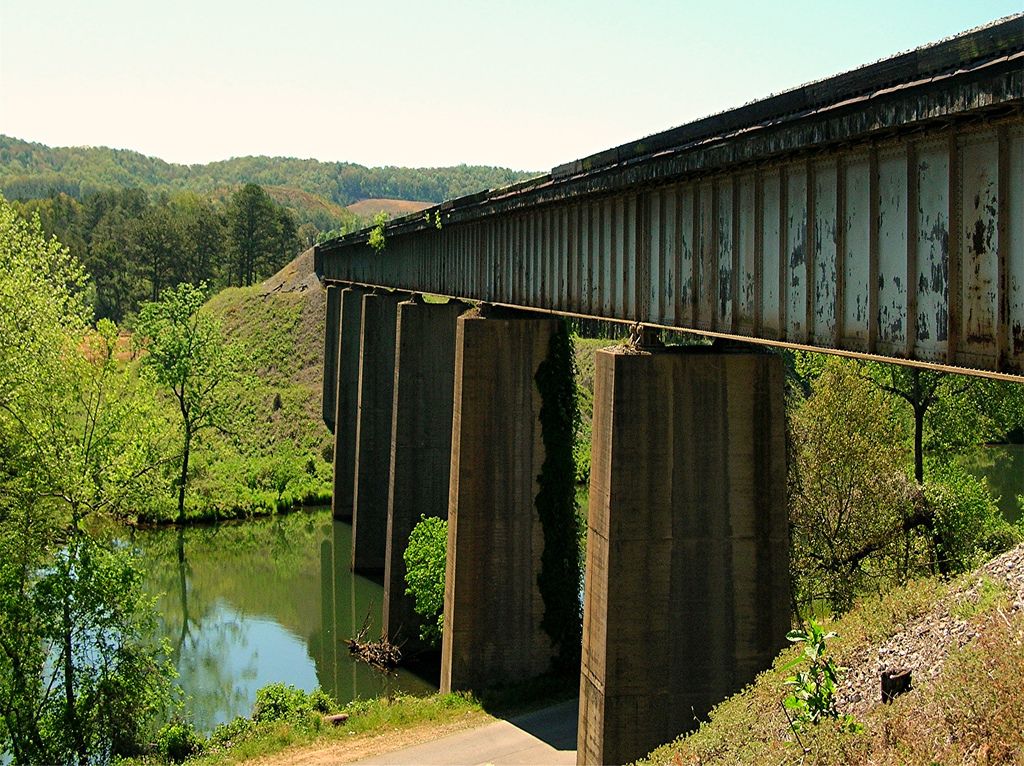
The prototype bridge is a seven-span ballasted deck girder bridge. The bridge crosses not just the Etowah River, but also Old River Road, which runs along the banks on the north side of the waterway. The approaches to the bridge are built on a high fill that is completely covered in a layer of lush Georgia kudzu. Most of the surrounding area is rural, with a low-lying pasture featuring a picturesque red barn located along the north shore along Old River Road.

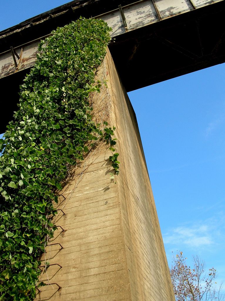
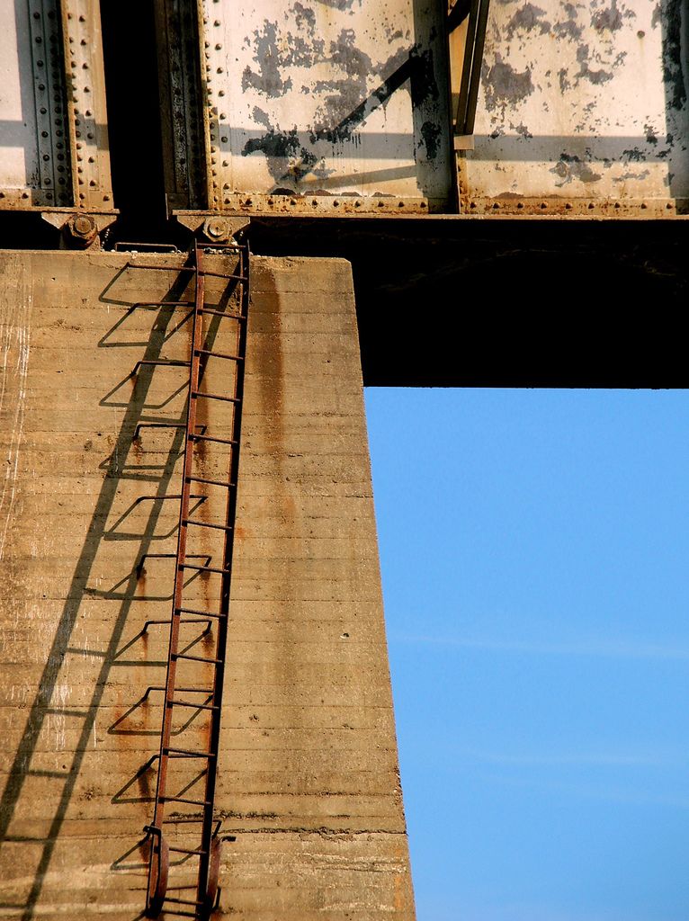
The basic bridge construction is fairly typical: a ballasted deck made of railroad timbers laid across a pair of steel plate girders, which in turn rest upon tapered concrete piers. Some of the unique features of the bridge include a cableway running along the west side of the girder face, grab irons mounted on the west faces of the piers, and the lack of any railings or walkways. At one time, ladders extended to the bridge deck from the tops of the piers, but at some point these were cut free and left hanging off the top of the piers. Given the lack of railings and walkways, I would be interested in knowing what happens when a conductor must walk a train stopped across the bridge.

Photos below by Kenny Shackleford via Flickr, used by permission.
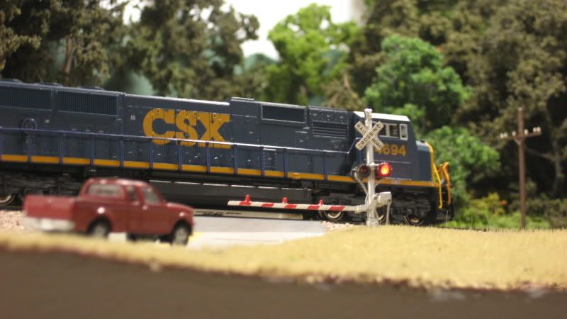
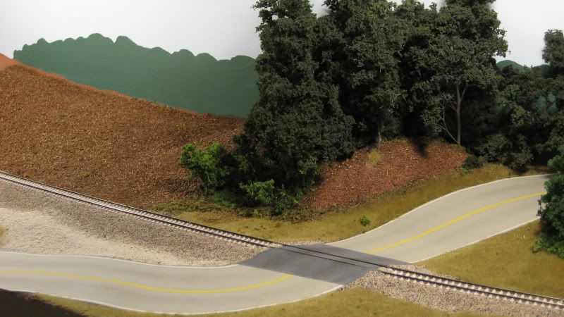
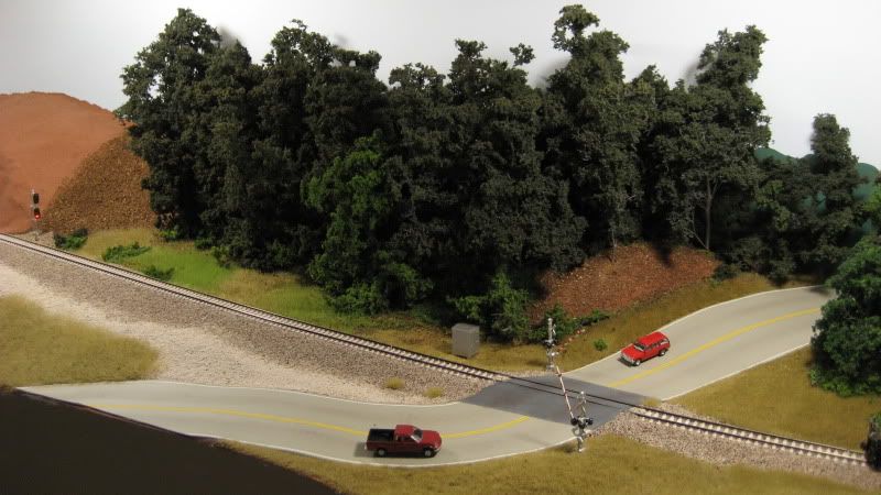


» The Model


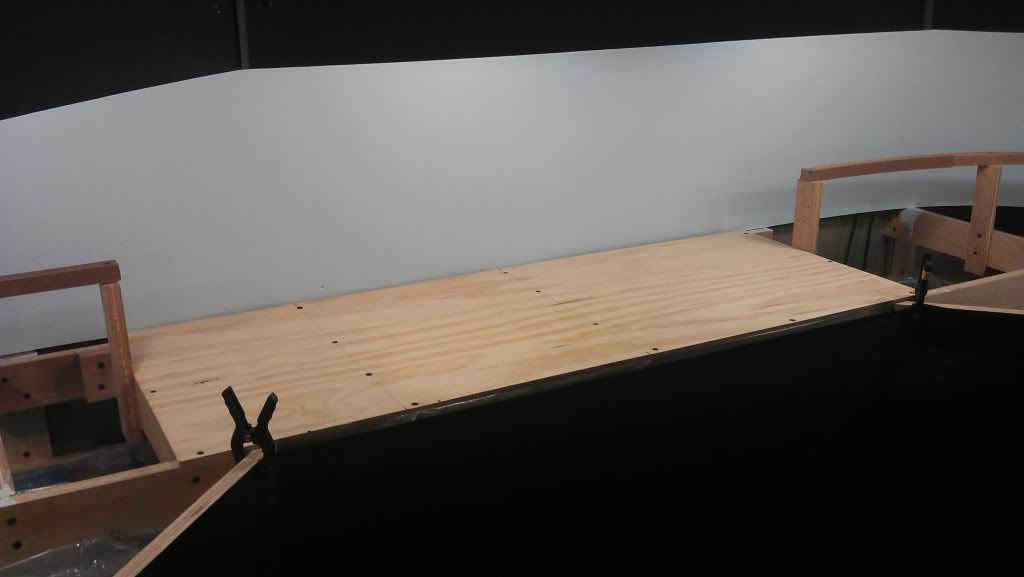
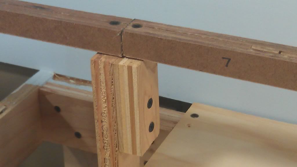
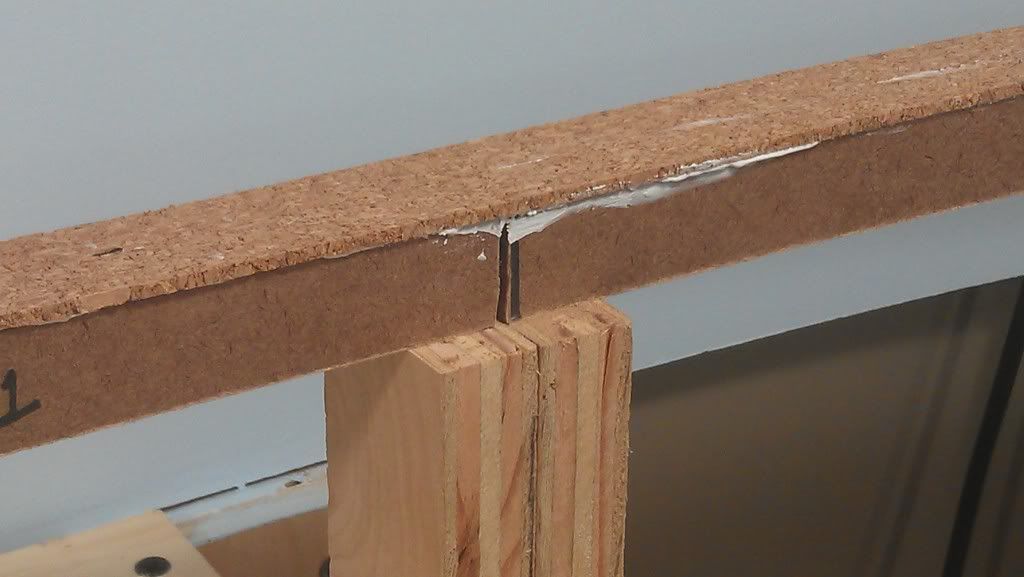
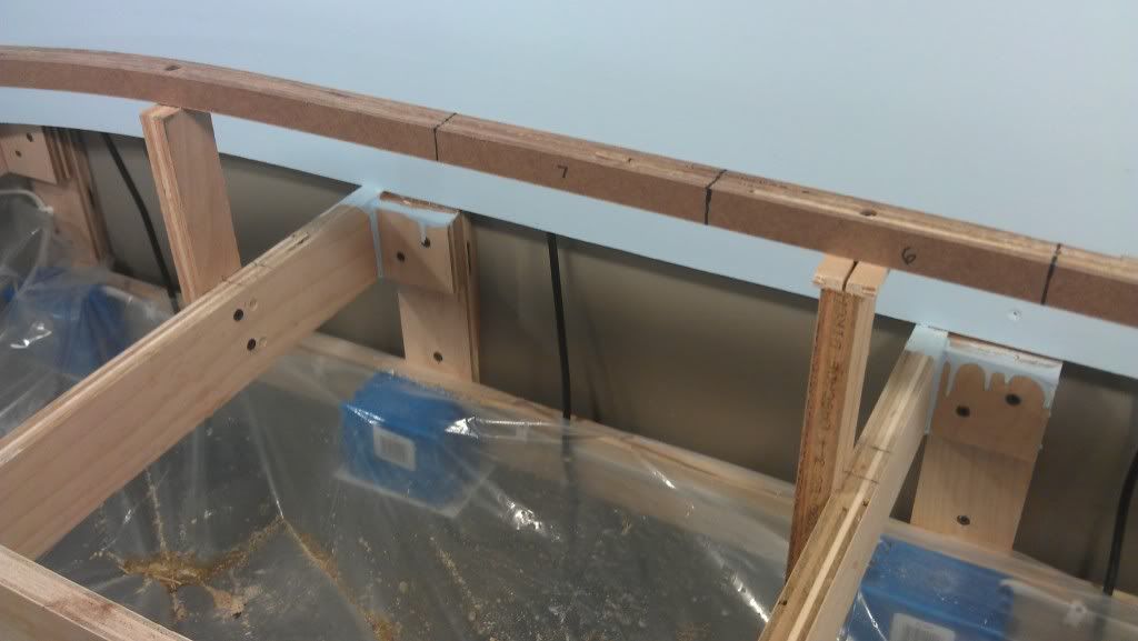
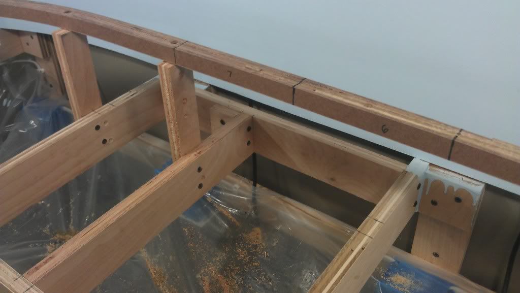
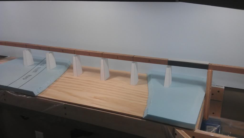
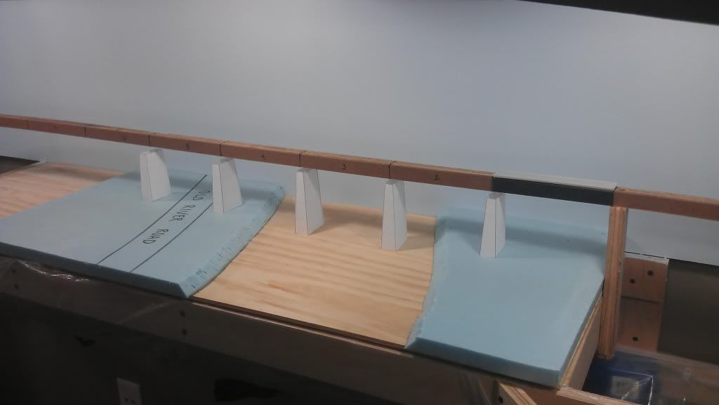
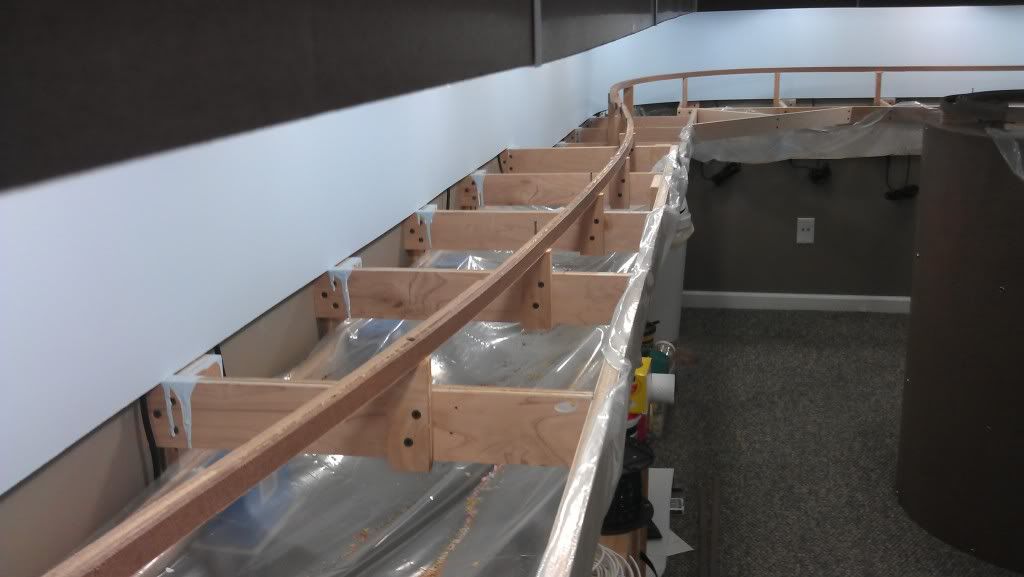
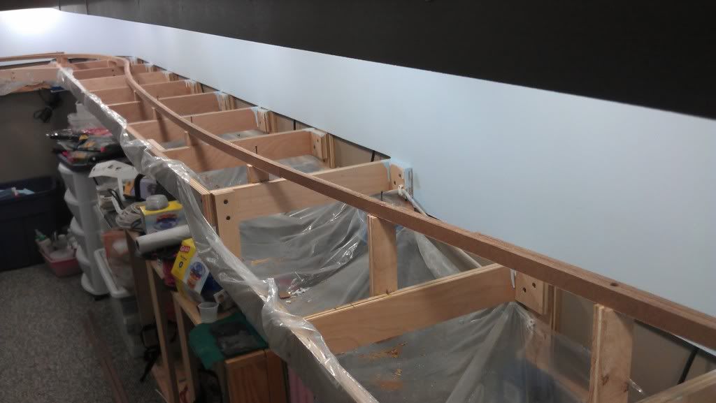
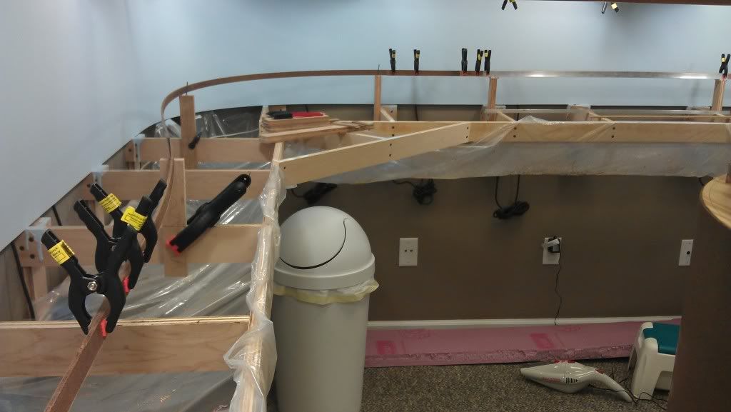
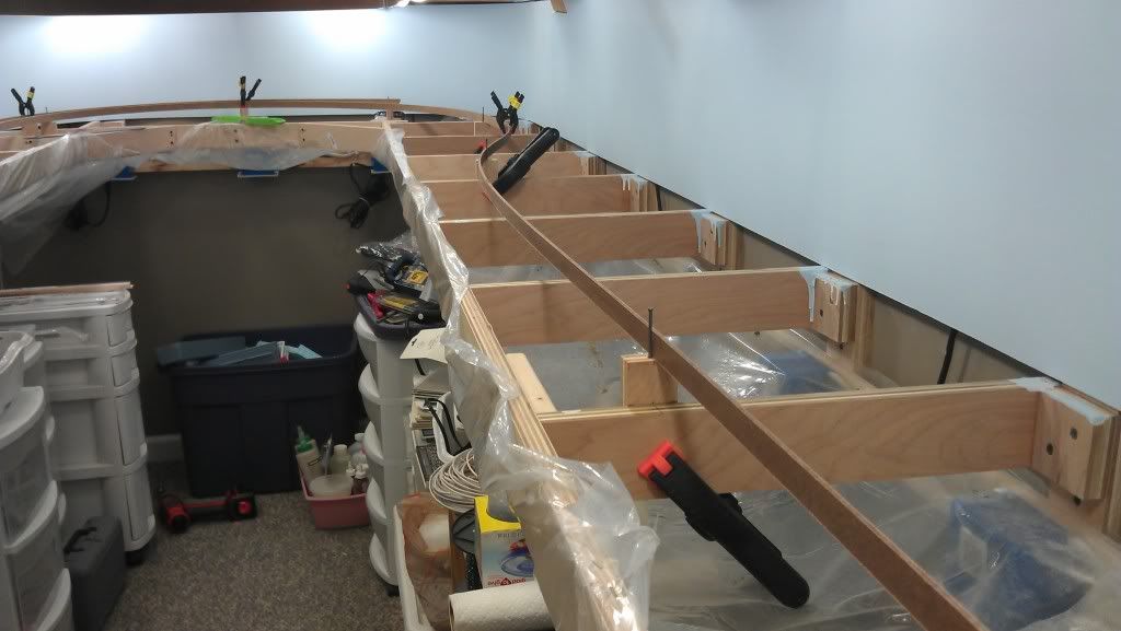
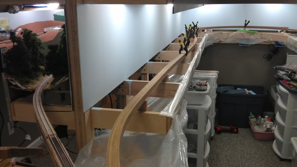
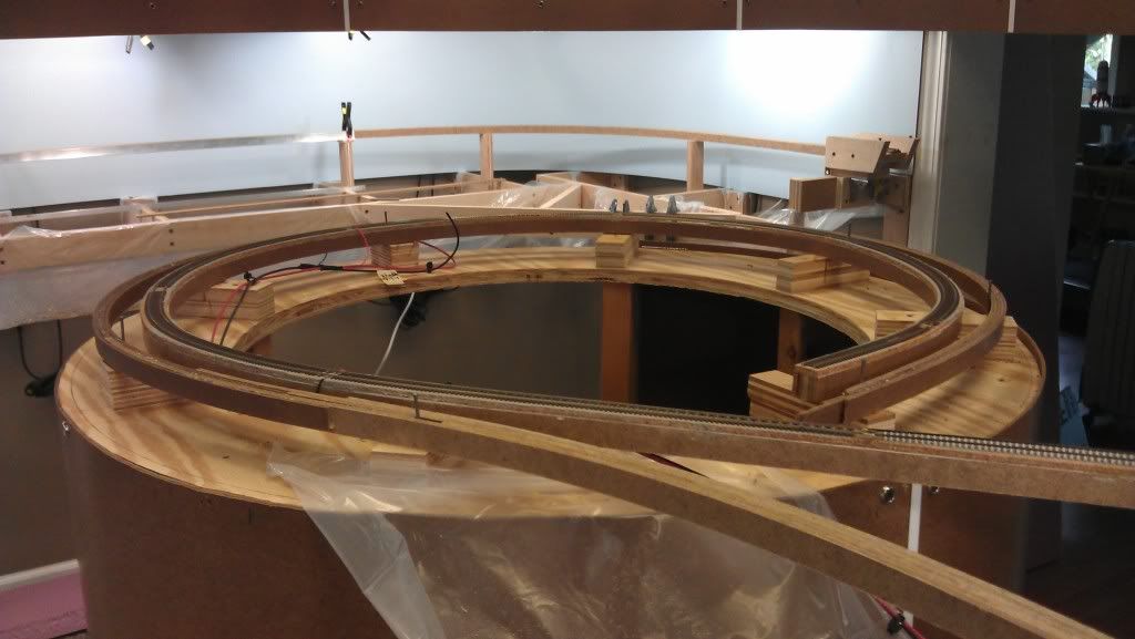
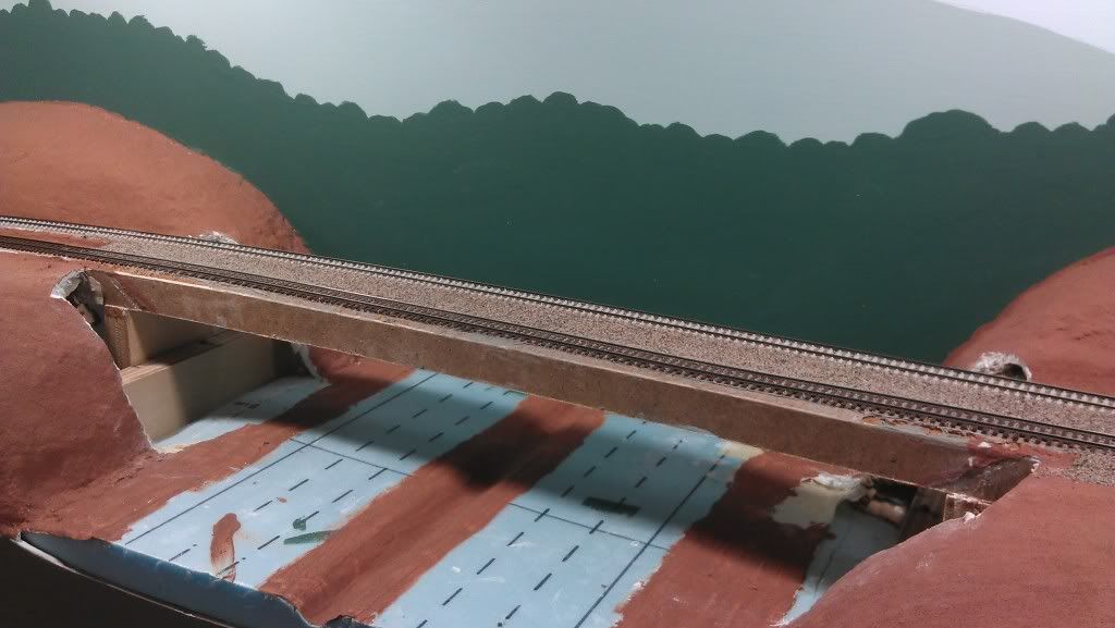
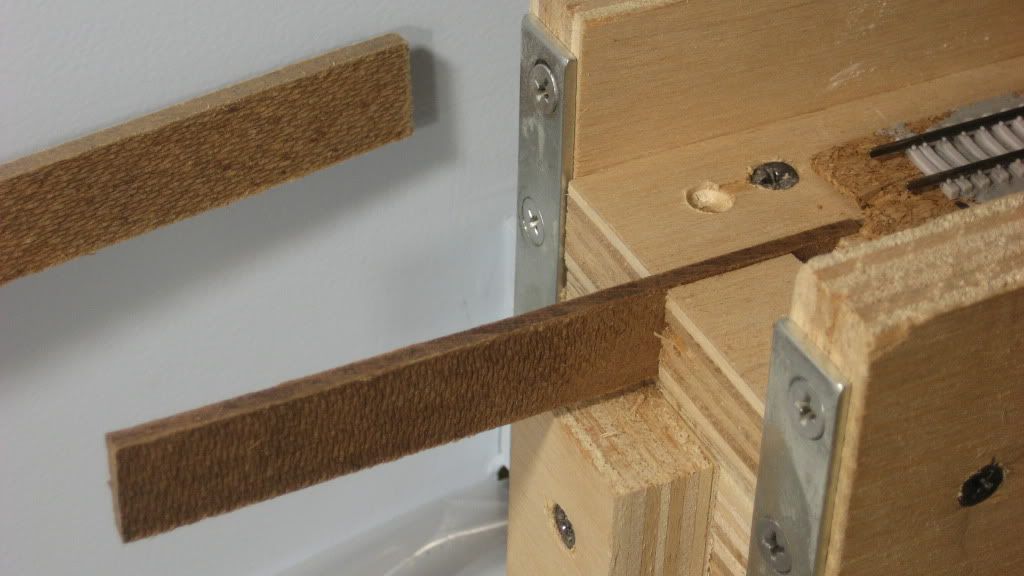
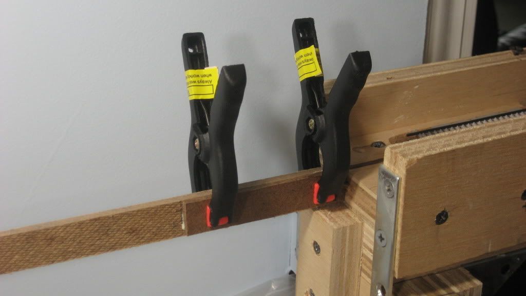
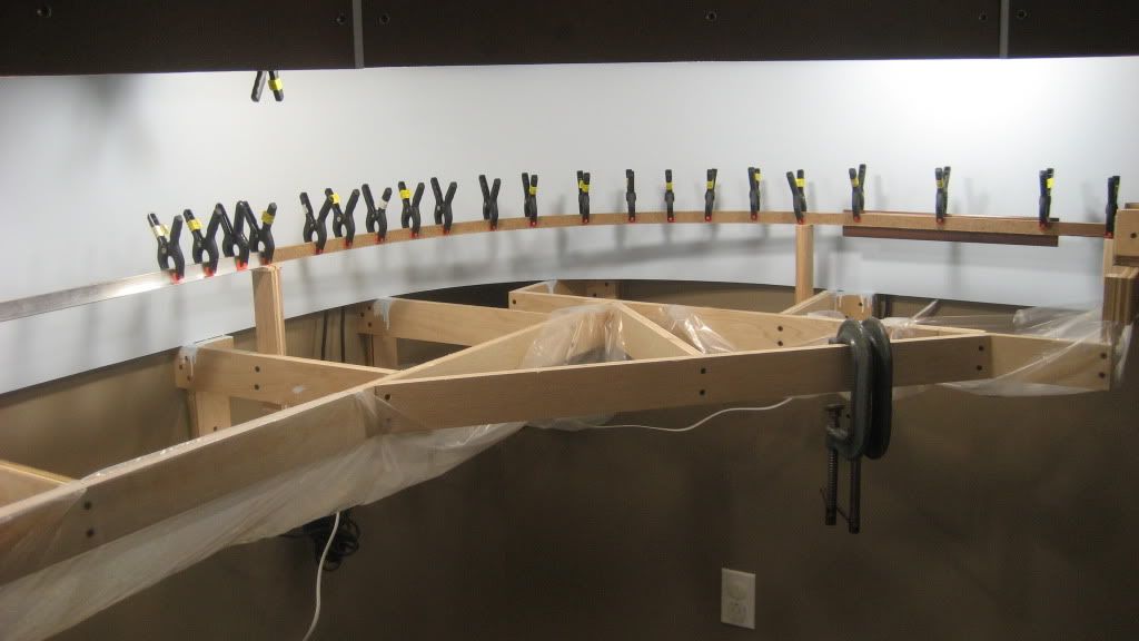
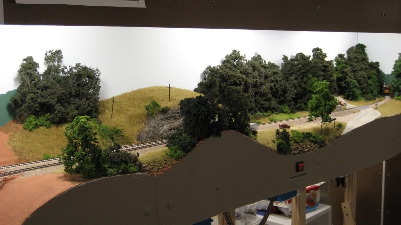
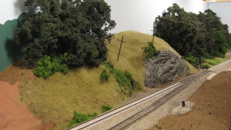
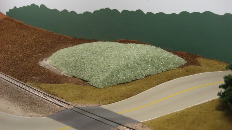
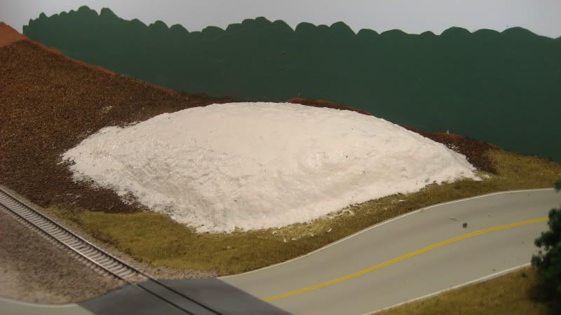
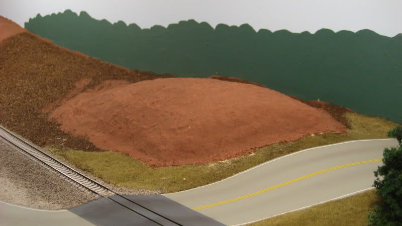
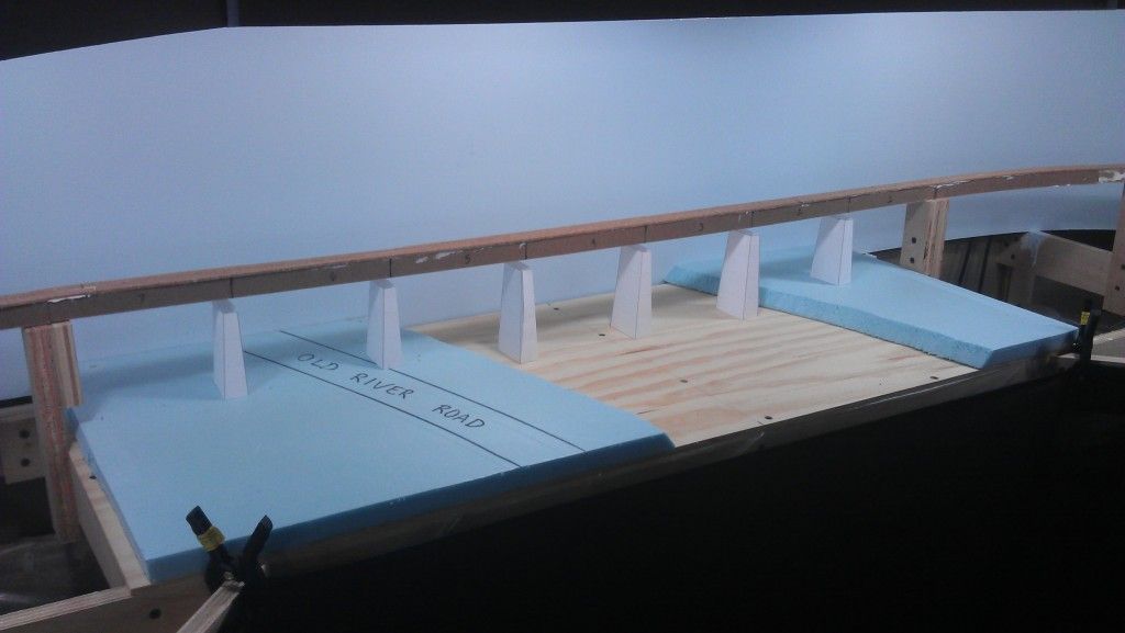
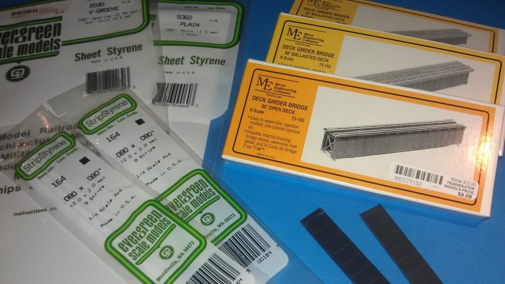
The model bridge will also be a seven-span ballasted deck girder bridge as mocked up in the photo below. The bridge itself will be kitbashed from seven Micro Engineering 80' deck girder bridges. The girders from the kits will be used, while the deck will be scratchbuilt. The piers and abutments will be cast in plaster using scratchbuilt molds. The bridge must be constructed so that the top of the deck lines up with the top of the spline roadbed approaches. This will allow cork roadbed, track and (eventually) ballst to be laid across the bridge and approaches in a continuous manner. My standard cardboard web, plaster cloth and Sculptamold terrain will be used to simulate the high fill found on the prototype. Finally, the surface of the plywood riverbed will be sanded and painted, then covered with Envirotex to simulate the water. The Etowah consistently has a deep green color in this area and is often quite calm, so the Envirotex should do an excellent job of simulating the river in this scene.

The next posts in this series will chronicle the construction of the Etowah River bridge on the layout over the coming weeks.


.

Monday, January 2, 2012

Layout Progress as of 1/2/2012

I have constructed a temporary bridge over the Etowah River. This structure will serve as a stand-in until the actual bridge can be constructed at a later time. The temporary bridge will allow the mainline track to be completed on the lower level and was constructed using the recycled section of spline roadbed that previously spanned the river. Eventually, seven ballasted deck girder bridge spans will rest on concrete piers in this scene.

» Photos


This photo shows how a 42" length of the existing spline roadbed was cut out where it spans the river. I have also installed 1/4" plywood to support the river bed:


This closeup photo shows how the left (north) end of the temporary bridge roadbed is supported on a cleat temporarily screwed to the permanent riser:


This closeup view shows the right (south) end of the temporary bridge roadbed with the first layer of cork roadbed installed across the gap:


.

Wednesday, December 21, 2011

Layout Progress as of 12/21/2011

I have decided to go with the full length seven-span Etowah River bridge as discussed in the previous update. With the bridge length determined, I had to add support to the roadbed at the north end of the structure. Eventually, the spline roadbed will be cut away and replaced with a 42" length of aluminum channel. The deck girder bridge will then be built in place around the channel and cast plaster piers will be added below.

» Photos


This "before" photo shows the original roadbed support before the bridge length was determined:


This "after" photo shows the additional benchwork constructed, including the riser that supports the roadbed at the north end of the bridge:


The additional benchwork will also support the 1/4" plywood that will make up the river bottom.

.

Sunday, December 18, 2011

Layout Progress as of 12/18/2011

While working on the Etowah River scene, I realized some additional benchwork needs to be added around the bridge before track can be installed. Before adding the extra support, however, I needed a way to see exactly where it has to go. To do this, I created some full-size mockups of the bridge scene. The actual bridge is comprised of seven deck girder bridge sections supported by concrete piers. I will eventually be using Micro Engineering 80' ballasted deck bridges supported by cast plaster or cement piers. The following two photos show the mockups I did. The first photo shows the complete non-compressed bridge (seven sections), while the second photo shows a compressed version of the scene with only six sections (one section over the river removed):


I wanted to try out the compressed version because I believed the full size bridge would be too big. Also, six 80' deck bridge sections comes out to an even 36" in N-scale, which means I could use one 3-foot length of aluminum U-channel to be the supporting backbone of the bridge. However, when looking at the two photos the river just seems too narrow in the compressed version. I am also considering using a compressed bridge with the full-size river; in this case, the road would be eliminated. This option is probably not going to be selected because that road is one of my first ever railfanning locations and is a significant reason why I chose to model this area in the first place.

Whatever option I choose, the mockups are a quick way to visualize a completed scene without too much effort (time or money).

.

Wednesday, December 7, 2011

Layout Progress as of 12/7/2011

A significant milestone was reached on the CSX Dixie Line this week when the final mainline roadbed was installed on the lower level of the layout. There is now continuous spline roadbed from Emerson, GA at the south end of the lower level all the way to the helix at Tilton, GA at the north end of the lower level. This clears the way to finish designing and intslling roadbed for the remaining sidings and industry tracks on the lower level.

» Photos


Looking north from the dropdown gate (far right) to the Etowah River bridge:


Etowah River bridge:


Looking south from over Calhoun, GA to the Etowah River bridge (distance):


Looking south over the entire Calhoun, GA scene:


Looking north over the entire Calhoun, GA scene:


Looking south over the Tilton, GA scene towards the end of the aisle. The north end of the Resaca passing siding is in the foreground, while the siding itself curves around and ends (for now) before reaching Calhoun:


Looking north over the Tilton, GA scene towards the Helix. The Etowah River bridge can be seen in the distance beyond the helix:


.

Sunday, December 4, 2011

Layout Progress as of 12/4/2011

My current project is to get all of the the lower level track installed. Trackwork has been in place for almost two years on the Emerson, GA scene, which is the southern most scene on the layout. The following photos show all of the new spline roadbed that I have been working on moving north from Emerson.

» Photos


The first scene north of Emerson is Etowah River. In this photo, you can see the completed spline roadbed along the long curve connecting the dropdown gate across the doorway to the train room (far right) with the Etowah River bridge (far left):


Here is a straight on view of the bridge. This will be a five span deck girder bridge when completed:


North of the Etowah River is Calhoun, GA. I have not yet finalized the design in this scene; you can see in the photos where I have risers temporarily clamped in place so I can move a spline around to experiment with different track alignments. This view looks south with the Etowah River bridge in the distance:


Looking north at the same scene with the temporary track alignment:


Just to the north of Calhoun is Tilton, GA. This is the final scene on the lower level before the track disappears into the helix on its way to Chattanooga, TN. Spline roadbed construction is well under way in this scene:


Looking north at Tilton toward the helix you can see the newly completed spline roadbed in the foreground leading to the double track helix. The completed track connects the helix to Emerson; you can also see the new spline roadbed at Etowah River in the distance:


.

Wednesday, September 28, 2011

Layout Progress as of 9/28/2011

I have started work on the bridge where the CSX W&A Subdivision crosses over I-75 in Emerson, GA. I will be building this bridge in place; in other words, the bridge will be built around the existing spline roadbed. The only work completed so far is the removal of the scenery base where the bridge abutments will be installed:


Below, I have included a few pictures of the prototype structure courtesy of Google Maps and Bing Maps. The scene on the layout will be simplified compared to the prototype scene in that there will be no off ramps modeled. Instead, there will be two three-lane interstate roadways and three bridge piers.

Looking northbound from the on-ramp from Old Allatoona Road to I-75 northbound:


Looking southbound from the off-ramp from I-75 southbound to Old Allatoona Road:


Overhead view looking northbound:


.

Tuesday, April 12, 2011

Layout Progress as of 4/12/2011

It has been over two years since any trackwork has taken place on the CSX Dixie Line, but that changed over the weekend as work started to extend the roadbed through the new Etowah River scene. The CSX W&A Subdivision crosses the Etowah River just to the north of Emerson, GA, and this prototypical arrangement will be represented in the same fashion on the layout. Over the next few weeks I hope to have all of the lower level roadbed in place so I can extend the mainline beyond its current terminus just north of Emerson.

» Photos


This photo shows how the spline roadbed is joined to the dropdown gate by inserting a short "key" section of spline into a slot cut in the deck of the gate. You can clearly see the northernmost extent of the mainline where it ends on the gate. The first spline to be attached to the "key" spline can be seen against the backdrop:


The first spline has been glued to the "key" spline and clamped in place:


Somehow, a few of my risers were a full 1/4" too low. This problem was corrected by gluing some small sections of 1/4" stripwood to the tops of the risers. The nail is centered on the riser and provides a surface for clamping the first spline in position:


The second spline has been glued and clamped in place. You can see the dropdown gate at far right and the future location of the Etowah River bridge at far left. The aluminum angle will keep the splines perfectly straight across the bridge:


.

Tuesday, November 30, 2010

Layout Progress as of 11/30/2010

Over the long holiday weekend, I added the remaining grass, bushes and trees to the area around the South Emerson turnout on the layout. Although there are still some details to be added, this scene is pretty much complete.

» Photos


Looking north at the South Emerson turnout:


The next photo is the same area as above but looking in the opposite direction:


.

Thursday, November 25, 2010

Layout Progress as of 11/25/2010

Happy Thanksgiving to everyone! Aside from consuming mass quantities of turkey and all the trimmings, I did some additional scenery work around South Emerson on the layout. I am mostly adding vegetation behind the tracks to the north of the rock cut and in front of the tracks between the Allatoona Road grade crossing and the I-75 overpass.

» Photos


Looking north at the South Emerson turnout, I have added gravel in front of the tracks where the signal relay shed will be located. The line poles can still be found along most of the right-of-way despite the fact that they were taken out of service sometime in the early 1990s. They are a prominent feature above the rock cut on the prototype as they are on the layout:


The next photo is the same area as above but looking in the opposite direction (south). The newly added scenery includes the cluster of trees and grassy hillside to the left, bushes and vines, and the ballast around the signals:


.

Sunday, November 14, 2010

Layout Progress as of 11/14/2010


Recent progress on the layout includes adding additional layers of vegetation to existing scenery, adding new vegetation to bare scenes, and adding a few details here and there. The photo above shows a good example of what I have been working on recently. Some of the new "little touches" that really impact the realism of this scene include:

  • The electrical box that houses the circuitry for the grade crossing signals

  • Additional bushes and shrubs around the base of the hill

  • Small tufts of dry grass in a few places


I still have to decide what to do with that bare patch of grass in the foreground. On the prototype, there is dense brush with a side street angling away. While the dense brush would obscure most of the scene, I am still contemplating adding a driveway and a few mailboxes to represent the street that leads to a few homes.

The next photo shows the same scene looking north towards the recently added rock cut that I described in another post. I have included a prototype photo to show how the modeled scene compares to the real thing:


Some of the work I have done in this area includes:

  • Adding static grass to the hill above the rock cut

  • Adding bushes, weeds and vines between the tracks and the trees

  • Adding static grass down the center of the access road

  • Adding the CSX "No Trespassing" sign from a digital photo

  • Adding tress and bushes in front of the tracks


While this scene looks complete, if you look closely you can see bare ground extends past the grass covered areas. I still have lots of vegetation to add to this scene, plus I am working on a concept for adding high tension power lines that cross the tracks at the rock cut.

.

Friday, October 29, 2010

Layout Progress as of 10/29/2010


Trees, trees and more trees. This week I found out that you can crank out a lot of SuperTrees while watching Monday Night Football and the 2010 World Series. As a result, I added a significant section of forest (about 18" long) behind the tracks at South End Emerson. I also installed working grade crossing signals (above), which will be covered in detail in an upcoming HOWTO post. The photos below show an overview of the progress made this week.

» Photos


Before:


After:


.

Tuesday, October 19, 2010

Layout Progress as of 10/19/2010


I recently finished some scenery work that I started way back in...July? Can that be right? Three months away from the layout? This was a busy summer. Anyway, while looking at some prototype photos of the Old Allatoona Road grade crossing, I noticed the road actually travels through a slight cut after crossing the tracks. Although the cut is low, it is quite noticeable (as you can see in the Google Maps imagery below) and modeling it would be a nice way to tie the layout to the real thing. The photos below show how I modeled this feature.


» Photos


I began building the hill behind the tracks by shaping some plain old green floral foam. I carved the hill to shape before affixing it to the layout using Loctite construction adhesive. I applied the hill right over the top of the existing scenery base, which had already been covered with dirt and some static grass:


I then covered the hill with Sculptamold to blend it in to the surrounding terrain. Since all of the hill except for the cut face along the road will be covered by foliage, I didn't spend too much time on this step:


Next, the hill was painted using my standard textured ground color:


Finally, the usual treatment of ground cover, bushes and trees were added. I rubbed most of the ground cover off of the cut face of the hill to reveal the red Georgia clay just as it appears on the prototype:


This small change resulted in a big improvement to the look of this scene.

.