Thursday, August 28, 2008

Layout Progress as of 8/28/2008

This week I started installing the lighting for the CSX Dixie Line layout. For my lighting solution, I decided to go with compact fluorescent lighting (CFL). I estimate I will have about 70 lighting fixtures on the layout, so the choice to use CFLs was an easy one since they use little power and generate little heat. For example, I am using 40-watt equivalent CFL bulbs--this means the light output of the CFL is comparable to that of a 40-watt incandescent bulb, although the CFL actually uses only 9 watts to produce the same amount of light. Using 70 40-watt incandescent bulbs, I would be drawing a whopping 2,800 watts just for the layout lighting! However, by using CFLs, I am only consuming 630 watts. Plus, the heat generated by those 70 incandescent bulbs would turn the layout room into a walk-in easy bake oven!

Of course, while I determined CFLs to be ideal in this situation, they are not the perfect choice. Most CFLs are not dimmable, and the ones that can be dimmed are quite expensive and unreliable. Also, the color choices available in CFLs are limited. This latter problem is not much of an issue since "soft white" CFLs have recently become commonly available at all of the big box home improvement stores.

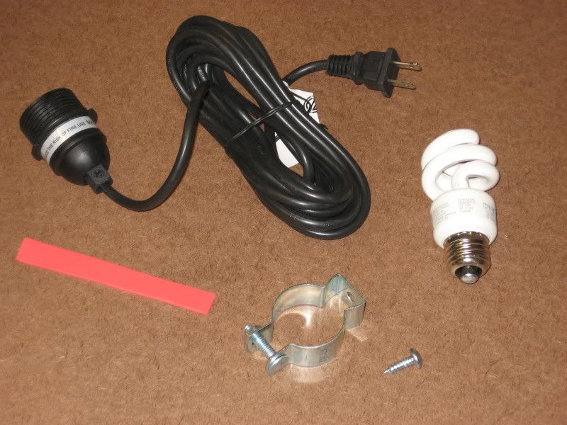
The first picture shows all of the components I use for a single light (clockwise from top): light socket with 15' plug in cord, 9-watt "soft white" CFL, #14 x 3/4" wood screw, 1 1/4" conduit hanger and a small strip of craft foam. The lighting fixtures were purchased from Ikea for about $4 each and are readily available on the Ikea website.


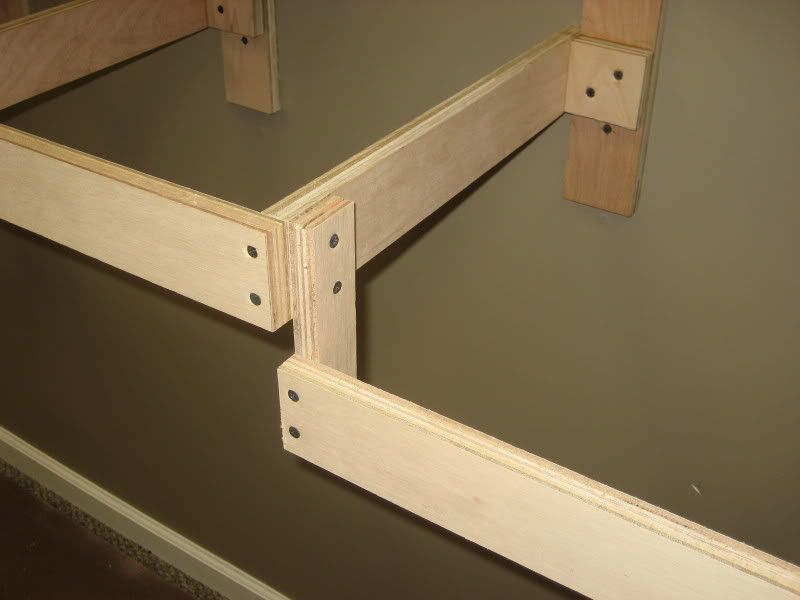
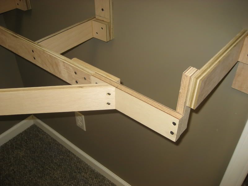
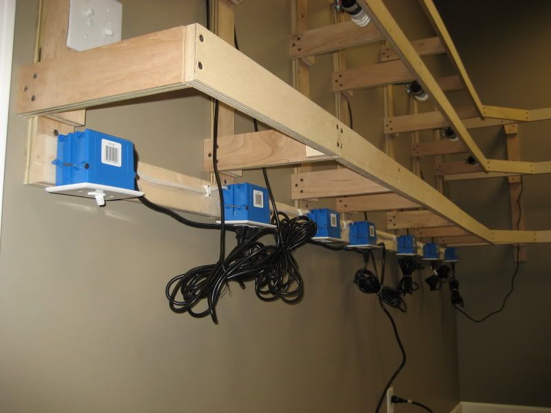
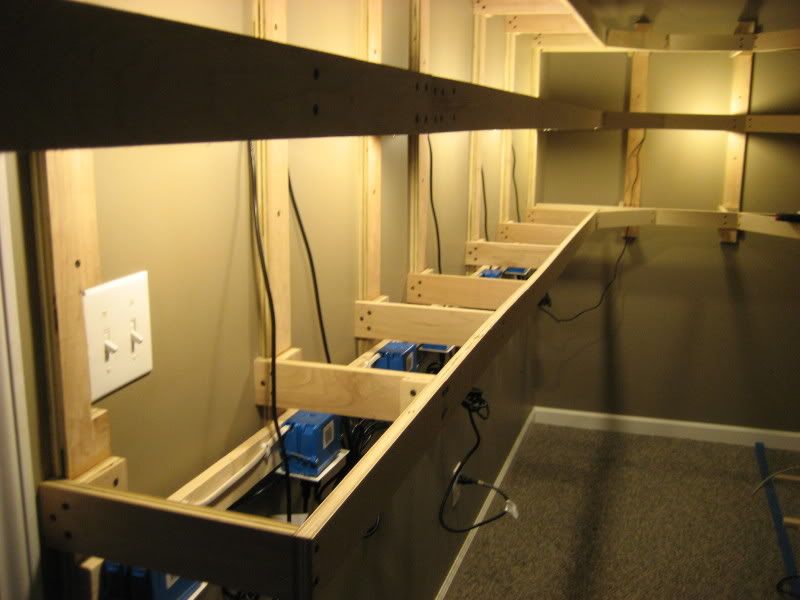
To distribute power around the layout for the light fixtures, I am building a "power strip" along the bottom of the layout all the way around the room and down the peninsula. The picture below shows the first section of this power strip. The blue box at the far left in this picture is for a light switch that allows all of the layout lights to be turned on/off from a single point. You can also see where the power strip plugs in to a standard wall outlet using a 14 gauge cord. There will be a double receptacle installed at the bottom of each wall bracket and on each peninsula support. The cords running down from the fixtures to the power strip will be covered by the layout backdrops, while the power strip and the bundles of excess cords will be hidden by the layout skirting that will hang from the lower level. In this picture you can also see four of the lighting fixtures that have been installed under the benchwork for the middle level of the layout:


This picture shows a closeup from below of one of the installed lighting fixtures. You can see how I used the small strip of craft foam between the fixture and the conduit hanger. This piece of foam allows the conduit hanger to better "grip" the fixture so that it will not slide around or come loose over time:


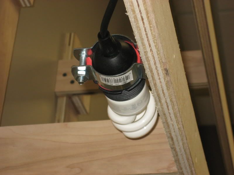
Here is the same lighting fixture shown in the previous picture, this time viewed from above. Cable ties keep the cord secure and route it behind where the layout backdrop will be installed. You can also see two of the double receptacles installed at the bottom of each wall bracket along the power strip:


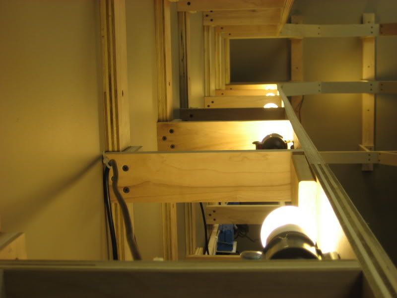
Here is the same light fixture once again, this time looking straight down through the upper level benchwork:


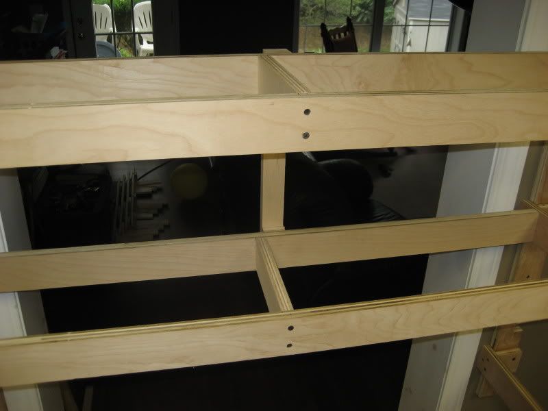
Here is a view looking along the benchwork for the middle level, showing the light fixtures that illuminate the lower level:


This is the same view as in the previous picture, except that the lights have been turned on:


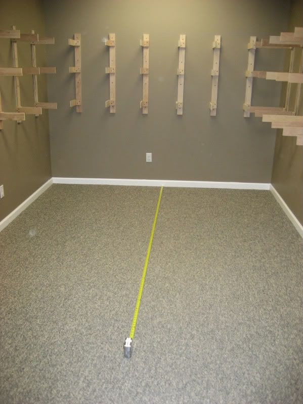
Here is an overall view of the lower level being illuminated by the newly installed lighting (the room lights are off in this picture). I currently have the fixtures installed at 2' intervals, but this spacing can easily be adjusted as needed. Next I will install and paint the backdrops which should allow me to determine if there are any bright or dark areas that will require adjustments to the fixture spacing.


.

Friday, August 22, 2008

Layout Progress as of 8/22/2008

This week I managed to finish all of the major benchwork on the CSX Dixie Line layout. This basically means all of the benchwork has been completed with the exception of two projects: the helix and the swing down gate into the layout room. It took exactly 4 weeks from starting construction to get to this point, which is pretty surprising considering I was planning on a couple of months for the wall brackets alone!

Looking down the aisle along the left side of the peninsula. Note the 1x2" brace across the top of the aisle to stabilize the end of the peninsula until it can be permanently attached to the future helix:


A closer look at the end of the aisle along the left side of the peninsula:


Looking down the aisle along the right side of the peninsula. A temporary 1x2" brace similar to the one in the previous photo also goes across this aisle:


A closer look at the end of the aisle along the right side of the peninsula. You can clearly see where I extended the depth of the layout to a full 24" at the end of this aisle. This will allow for some foreground structures or scenery to be placed to break up the horseshoe curves the mainlines will need to make on both levels:


Looking up from the end of the aisle along the left side of the peninsula. You can see the doorway into the layout room and the location where the swing bridge still needs to be constructed on the lower level. The helix will be placed at the end of the peninsula, or just ahead and to the left in this view:


Looking up from the end of the aisle along the right side of the peninsula. This view clearly shows how the lower level drops down to allow for the elevation change between the town of Cartersville, GA and the Etowah River valley at the far end of this view:


A wide view of the wall opposite the end of the peninsula:


Here is a look at the angled inside corner extensions added to the benchwork opposite the end of the peninsula. An additional brace has not been added to the middle level because I am not sure whether or not it will interfere with the lower level lighting to be placed under the middle level benchwork:


A close view of the bracing added to the middle and upper levels to support track risers and scenery on both levels and the backdrop on the middle level:


Closeup of how the benchwork drops down on the lower level between Cartersville, GA and the Etowah River valley:


Closeup of how the angled extension joins to the benchwork and also how the benchwork drops down to the left of the doorway. You can also see a typical splice plate used to join the front boards where needed (in this case right behind where the angled extension joins to the front boards):


.

Sunday, August 17, 2008

Layout Progress as of 8/17/2008

This week construction continued to roll along on the CSX Dixie Line layout as I managed to completely build the peninsula that runs down the center of the room. Since I only had to build seven peninsula supports (as compared to a whopping 34 wall brackets!) everything came together pretty quickly.

Here is a "before" picture showing the layout room prior to starting construction of the peninsula. The peninsula will come off of the far wall towards the camera in the same orientation as the tape measure:


I built a single mock-up of a peninsula support using inexpensive pine boards to make sure everything would fit together before I built the actual permanent supports. My daughter lends a helping hand in making sure everything looks OK:


I first had to put the front boards on the wall brackets along the south wall since this would not be possible once the peninsula was in place. Also, these front boards will be used as anchor points to connect the peninsula to the rest of the benchwork:


I simply let the front boards cantilever off towards this corner to allow for future support for track risers or scenery in this area:


Next, I ran a 1x2" from the top front board out to the mock-up support. This temporary board will be used to correctly space the supports at 16" intervals along the length of the peninsula:


The temporary spacer board allowed for the peninsula to come together quickly. Here are the first four supports in place (click here for a detailed article on how I built the individual peninsula supports):


I had originally planned to tie the peninsula in to the rest of the benchwork by running the front boards along the peninsula all the way back to the front boards on the south wall. However, since this would be about an 8'-6" run, it seemed like I would have to do quite a bit of splicing on each of the peninsula front boards (which are only 8' long). Instead, I took the end peninsula support and rotated it 180 degrees so that the front boards on the peninsula would be 94 1/2", or just a shade under 8' long. This would mean I could use six trimmed 1x3s to make the peninsula front boards. Here is the first front board installed on the peninsula. Note that the support closest to the camera is facing the opposite direction from the others to allow 8' long 1x3s to be used for the front boards:


The blue painters tape provided a straight line for positioning the footers of the peninsula supports. After I put this line down on the carpet, I realized that the second support from the end was not coming close to lining up. Closer inspection revealed that the footer is about 2" off center from where it joins to the post. I'll probably need to trim off the opposite side since it now juts out into the aisle, but overall I'm pretty happy that this is the first significant blooper! You can clearly see the offending support in this photo:


Here is another view of the end support that clearly shows how it faces in the opposite direction from the others to allow 8' long (actually 94 1/2" long) 1x3s to be used for the front boards:


Here is the completed peninsula with all of the front boards installed. This side will feature Ladds, TN on the middle level and Acworth, GA on the lower level...


...while this side will feature Anderson, TN on the middle level and North Junta (Cartersville), GA on the lower level:


With all of the front boards on, I had to permanently attach the peninsula to the remainder of the benchwork. Remember at this point, the only connection point was the 1x2 temporary board running across the tops of the supports. To connect the peninsula, I first unscrewed the temporary top board and slid the entire peninsula off to the side:


Next I attached a 1x2 cleat to each of the front boards along the south wall:


I then slid the peninsula back in place and attached the peninsula using a pair of short 1x3s running from the cleats to the first peninsula support. This was done on all three levels and resulted in a sold connection. Here is a closeup of the connection at the lower level:


While the peninsula is now quite sturdy where it attaches to the wall end, it is a bit wobbly (top heavy) at the free end where it will attach to the helix. This was expected and will be resolved by adding a pair of braces across the aisles between the peninsula and the adjacent benchwork. Overall I am very happy with the progress of the construction so far--it took only 23 days to go from an empty room to where I am now. However, the next phase of construction--the helix--is sure to provide the stiffest challenge so far.

.

Friday, August 15, 2008

DIY: Build a Peninsula Support

This do-it-yourself article shows, in a detailed step-by-step fashion, the process that I used to build the peninsula supports for the CSX Dixie Line benchwork. I have found information such as this very helpful to me along the way, and I hope that by passing along my procedures, others will benefit from this information as well. As always, please feel free to post any comments/feedback via the links at the bottom of the article.

For a similar HOWTO article on building the wall brackets you can click here.

Step-by-Step in Pictures

Picture 1 Unlike the wall brackets, which were entirely constructed from 1x3" boards, the peninsula supports are built from both 1x2" as well as 1x3" boards. The primary structural member in the supports is the 2x2" post. This post is made by laminating two identical 1x2" boards together using both screws and glue. Both of these 1x2" boards have been cut to 68 1/4" in length. Remember, the top deck of the layout is at 69", but we use 68 1/4" since the post will be resting on a 1x2" footer which is 3/4" in height, so this footer will raise the top of the post to the correct 69". Here is the post already laminated together--I used 1 1/4" coarse thread drywall screws about every 12" and a liberal bead of glue:


Picture 2 Here are all of the components required to build one support. In the middle is the 2x2x68 1/4" post we built in the previous step. To the left is the 1x2x27 3/4" angle bracket, the 1x2x22" footer, and to the right are the three 1x3x20 1/2" joists:


Picture 3 The next step is to install the footer board to the bottom of the post. The shelves along the peninsula are 11" on each side, so a peninsula support will be 22" wide (one 11" shelf on each side, or 11" * 2 = 22"). Appropriately, the footer is 22" wide. I placed the laminated 2x2 post and the 1x2 footer together using a known square corner (in this case the factory cut corner of a sheet of plywood) so that the two pieces will go together at a 90 degree angle. I placed the cut edges of the post facing up simply because I thought this would yield better lateral stability to the peninsula; in fact it may not matter. Here are the two pieces positioned ready for assembly. Note that the footer has been marked at its midpoint and aligned with the center of the laminated post:


Picture 4 To assemble the footer to the post, I drilled a pair of countersunk holes through the bottom of the footer into the post, applied glue, and then secured the footer using two 1 1/4" coarse thread drywall screws. After wiping away excess glue, I slid the assembly away to show how the two pieces look after being joined together:


Picture 5 Next I secured the 1x2 angle bracket to the footer/post sub-assembly. The angle bracket provides additional stability to the support by assuring the footer and post remain at a 90 degree angle. Note that one end of the angle bracket has been cut at a 15 degree angle so that it will not interfere with the support sitting flush on the floor of the layout room. To attach the angle bracket, I slid the post/footer sub-assembly back against the sheet of plywood and applied pressure to both the post and footer with my feet to keep them snug against the sides of the sheet of plywood. I then attached the angle bracket to the footer two inches in from the end of the footer using a single screw, then swung the angle bracket over the post and secured it with two screws. Here is the completed post/footer/angle bracket sub assembly still positioned snugly against the sheet of plywood used to keep the whole sub-assembly square:


Picture 6 Now it is time to attach the three 1x3x20 1/2" joists to the support. Note that the joists have been cut to a width of 20 1/2", even though the double 11" shelves suggest a width of 22". However, each of the two shelves will have a 3/4" thick front board attached to the joists, so to accommodate one of these front boards on each side, the actual joist length has been reduced to 20 1/2". The first step is to mark the positions of the tops of the three joists on the laminated pole, at 42", 57" and 69" above the floor level. You will not need to mark the top since the support is 69" tall and the top joist will just be flush with the top of the post. Begin assembly by marking the locations of the three screw locations on the joist, but only drill a countersunk hole for one screw at this time. Then apply glue to the area where the joist will be mounted to the pole. I have also marked the location of the bottom of the joist on the pole so I know how far down to apply the beads of glue:


Picture 7 Next attach the joist to the pole using a single 1 1/4" coarse thread drywall screw. After wiping away excess glue, use a square to make sure the joist is on the pole at a 90 degree angle. By using just a single screw, the joist can be pivoted to the correct 90 degree angle position. Finally, drill the other two countersunk holes on the marked locations...


Picture 8 ... and attach the final two screws:


Picture 9 Repeat the process for the remaining two joists:


Picture 10 Here is the completed peninsula support ready to be installed on the layout (or you could add some insulators and wires and have some nifty 1:4 scale model railroad telephone/telegraph poles!):


.

Sunday, August 10, 2008

Layout Progress as of 8/10/2008

This week I finally spent some time working on version 2.0 of the CSX Dixie Line track plan. As a result, I did not spend a lot of time on actual construction. However, the work I did do resulted in a significant milestone: the remaining six brackets on the west wall, which brought the final number of wall brackets to 34, marked the completion of installation of all wall brackets.

This view shows the completed west wall (to the right) looking towards the south wall at the far end of the room. Along the west wall here, Cartersville, GA will be on the lower level and Stevenson, AL will be on the middle level:


Now I am facing the north wall at the far end of the room; the recently completed west wall is now on the left. If you look closely, the lower level drops down about three inches as it nears the north wall. This marks the spot where the town of Cartersville, GA ends and the Etowah River valley begins:


.

Friday, August 8, 2008

Track Plan v2.0

This version of the track plan includes several major revisions, so I bumped the version number up from 1.0 to 2.0. First of all, the plan now includes the adjusted layout dimensions: 11" deep shelves along two of the walls and the peninsula, and 17" deep shelves along the other two walls. Also, the entire overall plan has been rotated 180 degrees so that the peninsula now attaches to the opposite wall from the previous plan. This was done since the resulting shape of the new alignment favored the positioning of the towns I am planning. Finally, the plan actually includes specific towns, industries and other geographical features (although not all features to be included have yet to be identified or included on the plan).

While the track positioning has now been adjusted to more closely match what I envision to be the actual arrangement, it is still just a generalized routing and will most likely change once mock-ups and sample arrangements are done on the actual benchwork. Also, this plan is really just a "stream of consciousness" rather than a well refined work at this point. In other words, so far I have just thrown on every possible feature I could think of that would make sense in a particular location. However, like the track arrangement, I suspect many of the towns, buildings and other features will end up looking quite different from how they look on the plan at this time.

Let's take a look at each of the three levels in a little more detail.

Lower Level

The lower level of the layout represents a section of the CSX W&A Subdivision just north of Atlanta, GA on the way to Chattanooga, TN. The section I have chosen to model extends from Acworth, GA (milepost WA34.1) north to Cartersville, GA (WA47.6). This 13 mile segment goes through the rolling hills that are so prominent in the northwestern part of Georgia. The signature scene along this line is where the CSX crosses the Etowah River on a ballasted deck bridge just south of Cartersville. The town of Cartersville will be well represented, including the depot, county courthouse, and a pharmacy that features the official first Coca Cola wall advertisement. The area on the north end of Cartersville will feature the Goodyear Tire & Rubber plant, which in real life closed in 2003 but continues to thrive on the CSX Dixie Line. There does need to be some sort of small yard and a passing siding in this area, but it is yet to be mapped out in any detail. Also, the town of Acworth will probably be replaced by the town of Tucker, GA. Although Tucker is actually on the CSX Abbeville Sub east of Atlanta, it is adjacent to my current hometown and has several features I would like to model. I may actually combine Tucker and Acworth together--this area includes a passing siding but otherwise is undeveloped on the track plan.


Middle Level

The middle level of the layout represents a section of the CSX Chattanooga Subdivision just west (timetable north) of Chattanooga on the way to Nashville. The section modeled begins at Ladds, TN (milepost J133.8) and continues northbound to Anderson, TN (J102.2). This 31 mile section of the CSX "J-Line" dips down into the state of Alabama, and the two prominent towns featured on this level are in the Yellowhammer State: Bridgeport and Stevenson. However, the signature scene on this level is the CSX double crossing of the Tennessee River at Bridgeport: one on a deck truss span and one on a lift drawbridge span. This crossing also includes a long causeway across Nickajack Lake. Norfolk Southern has trackage rights on the CSX between Chattanooga and Stevenson, and this is true on the CSX Dixie Line as well. NS trains will enter CSX tracks at Stevenson and depart near Ladds, disappearing into some yet to be determined hidden staging arrangement so that NS trains never leave the middle level of the layout. Finally, the Sequatchie Valley Railroad (SVRR) junction with the CSX at the restored Bridgeport depot will be modeled along with the interchange yard. The SVRR mainline will terminate at a wall of the layout room, with the option for expanding this line into an adjacent room to connect to a future switching style layout.


Upper Level

The upper level of the layout will be used exclusively for staging. Two double ended staging yards are planned: the north yard represents Nashville, TN and other points beyond the northern end of the visible layout, while the south yard represents Atlanta and other points beyond the southern end of the visible layout. Each of these yards will have five tracks, although there is some space reserved for expansion of the south (Atlanta) staging yard. Three of the tracks in each yard are more than double the length of the average train, so serial staging (more than one train stored on a single staging track) can be used as well.


.

Sunday, August 3, 2008

Layout Progress as of 8/3/2008

Work this week was mostly made up of methodically continuing with the installation of the wall brackets for the CSX Dixie Line benchwork. At the end of last week, all of the wall brackets along east wall of the layout room were assembled and installed. All of the brackets along this wall are 11" deep since this is one of the narrow shelves of the layout. For a detailed look at how I build my wall brackets, click here for a step-by-step look with lots of pictures.

This past Tuesday night, I continued installing brackets that had been assembled the previous weekend. This allowed me to get the entire south wall of the room completed (this wall also employs the narrow 11" brackets). Here is a view of the completed south wall as viewed from where the helix will be located at the end of the peninsula that runs down the middle of the room:


Wednesday night I assembled the first "deeper" wall bracket for the north wall of the layout room. The north and west walls will have a depth of 17", allowing for some larger scenes to be located in those areas. After looking at the installed bracket, I realized it would interfere with the installation of the front boards on the brackets of the east wall. Although I could do this later, I went ahead and removed the bracket and did some work on the front boards on the east wall. This also meant I needed to do some of the benchwork across the doorway, since this would be much more difficult with the front boards in place.

Here is a high view of the basic benchwork across the doorway (the middle level will be a duckunder while the lower level will be a swing-out/drop-down gate, to be constructed later):


Here is a normal viewing angle showing the front boards on all three levels. Note that the lower level drops down here from the typical 42" lower level height to about 38 1/2" to accommodate a river valley scene:


Here is an overall view of the same area with the first bracket reinstalled on the north wall:


On Thursday evening, I finished the remaining brackets on the north wall:


The lower level on this wall is where the CSX crosses the Etowah River at Cartersville, GA on a high deck girder bridge. Just for fun, I decided to do a quick mock up of this scene:


And here is what I hope to have the same scene looking like some day (photo by Patrick Phelan via RailPictures.net; used with permission of the owner):


On Saturday, I began installing brackets on the west (and final) wall of the layout room. The entire 18' length of this wall will be 17" deep to allow for more scenery such as towns, industries and yards on all three levels. You can see the first three brackets have the lower level height at 39" to accommodate the Etowah River valley, while the remaining brackets have the lower level at the standard 42" height to accommodate the city of Cartersville, GA:


Finally, a wider view looking towards the north end of the layout room. The peninsula will attach to the wall where I am standing and will extend out towards the north end of the room, terminating with the double track helix. The only brackets remaining to be installed are the six along the west wall immediately to the left of where I am standing: