Wednesday, July 30, 2008

DIY: Build a Wall Bracket

This do-it-yourself article shows, in a detailed step-by-step fashion, the process that I used to build the wall brackets for the CSX Dixie Line benchwork. I have found information such as this very helpful to me along the way, and I hope that by passing along my procedures, others will benefit from this information as well. As always, please feel free to post any comments/feedback via the links at the bottom of the article.

Step-by-Step in Pictures

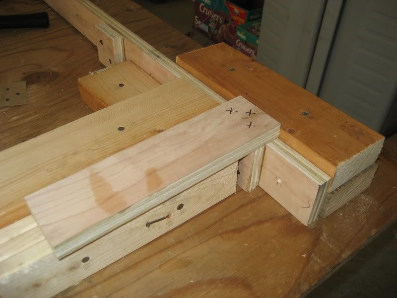
Picture 1 The first step is to cut the 1x3 stick lumber to the correct lengths. I actually use 1x3s ripped from birch plywood instead of standard dimensional pine lumber; this yields added strength and dimensional stability. This particular bracket will be 11" deep on all three levels, so the joists have been cut to 10 1/4" long (a 1x3 front board to be attached to the fronts of the joist is 3/4" wide and will bring the shelves to the correct 11" depth). Here are three joists, three cleats, and the 36" pilaster that will be used to build a single bracket:


Picture 2 Next, the correct locations for the tops of the joists and the pilot holes for mounting the bracket to the wall are marked on the pilaster. The tops of each bracket will be mounted on the wall along a chalk line snapped at 72" above floor level, so I take all of my measurements from the top of the pilaster. For example, the top level of the layout will be at 69" above floor level, so if the top of the pilaster will be 72" above floor level, I mark the location for the top of this joist 3" from the top of the pilaster. The remaining joists are marked at 15" and 30" from the top of the pilaster. The locations of the four pilot holes for the screws holding the bracket to the wall are marked at 2", 12", 22" and 33" from the top of the pilaster. Here is a photo showing a marked pilaster (note that the pilot holes are not centered on the long axis pilaster--this particular bracket is mounted next to a doorway and the only available wall stud requires the pilot holes to be 3/4" from the right edge instead of the usual 1 1/4" centered location):


Picture 3 This is a closeup showing the pre-drilled, countersunk hole for the top pilot hole in the pilaster. The nifty little tool is a quick-change drill/driver by Ryobi (I got mine at Home Depot), which allows you to quickly go back and forth between drilling pilot holes and driving screws without having to rechuck the bit each time. This is a real time saver!


Picture 4 Next the three cleats are attached to the pilaster. The cleats provide an additional surface to take the screws that hold the joist to the bracket, allowing for a much stronger joint. I have a jig that allows me to mount a cleat to a pilaster perfectly square each time. Here is the pre-marked pilaster inserted into the jig awaiting the first cleat:


Picture 5 This is the same picture as above except that the cleat has been placed in the jig for mounting to the pilaster:


Picture 6 After pre-drilling two countersunk holes through the cleat into the pilaster, I apply glue to the joint:


Picture 7 Next, the cleat is placed in position and attached with two screws. I use 1 1/4" coarse thread drywall screws for assembling the brackets. The excess glue will squeeze out and needs to be wiped off the bracket and the jig with a damp cloth (If you forget to wipe glue off the jig, it will get all over the next pieces you assemble and if a glob dries on the jig, the pieces may not fit into the jig correctly. Can you tell I found out the hard way?):


Picture 8 This picture shows the first cleat attached to the pilaster, which has been repositioned in the jig so the next cleat can be installed. The same process is repeated for all three cleats:


Picture 9 With all three cleats attached to the pilaster, the assembly is moved into a second jig I built to insure that the joists are accurately attached to the pilaster. Here is the pilaster placed in the joist jig ready for the top joist to be attached:


Picture 10 The first joist has been set into place and the locations for the three pilot holes have been marked. I have a cardboard template that allows these locations to be marked in the correct location each time (you can see the template laying on the work table at the upper left of the picture):


Picture 11 You can see the pilot holes have been drilled through the joist into the pilaster/cleat for the top joist and glue has been applied to the joint:


Picture 12 After glue has been applied, the joist is attached using three screws (again remember to wipe the excess glue off the work piece and the jig before moving to the next joist):


Picture 13 Attachment of the top joist has been completed and the pilaster has been repositioned in the jig ready for the next joist to be attached. All three joists are attached using the same process:


Picture 14 The jigs help insure that the assembly goes together quickly and perfectly square each time:


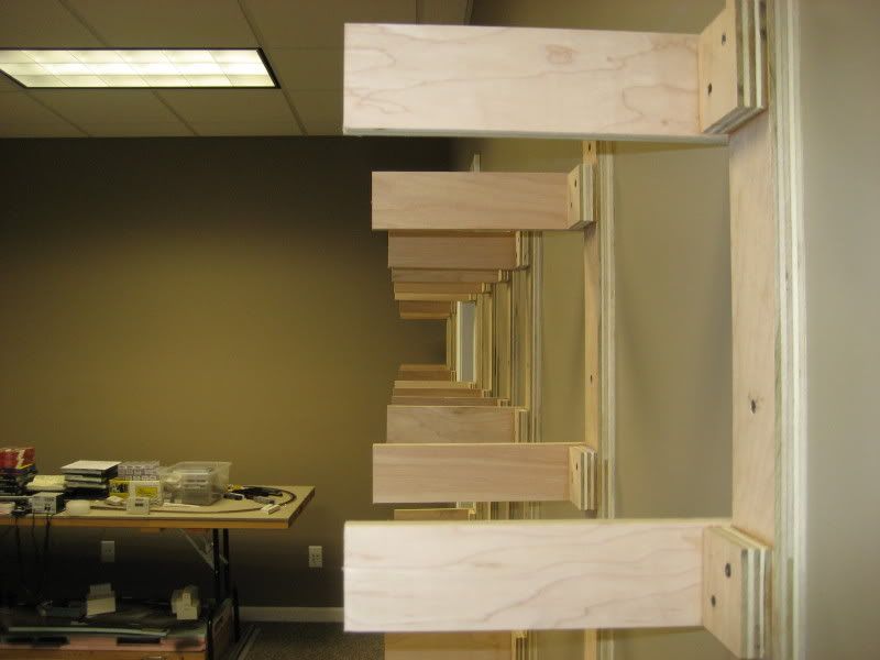
Picture 15 The finished product, ready to be mounted on the wall:


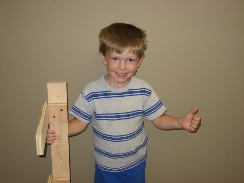
Picture 16 The crew foreman gives his stamp of approval to the first bracket:


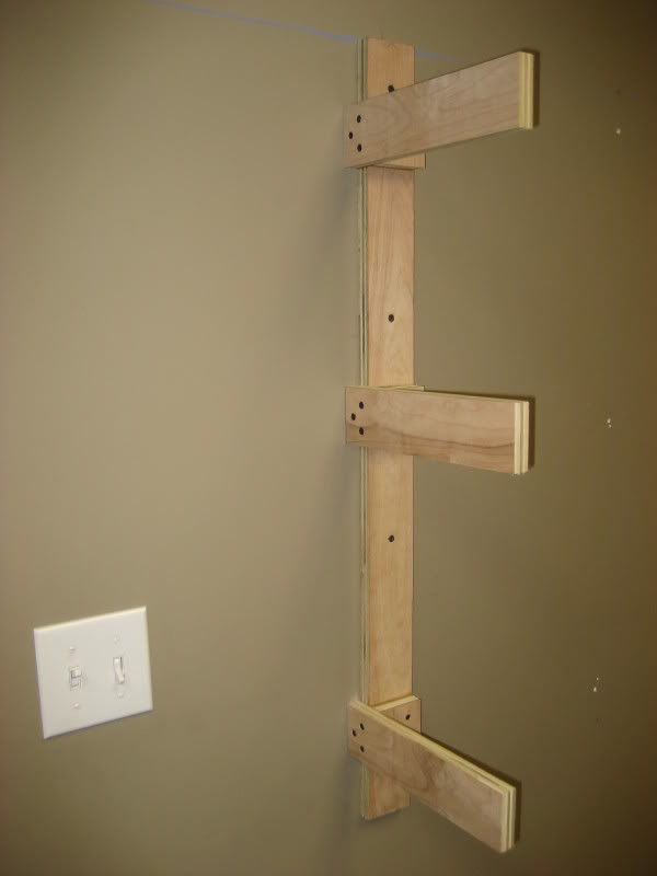
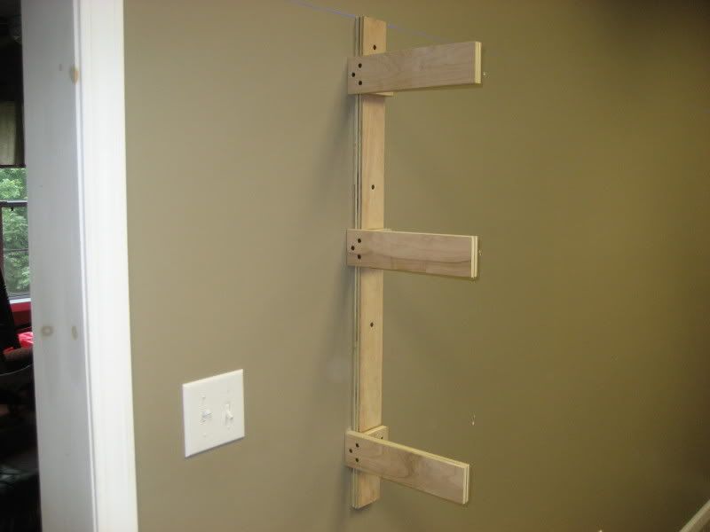
Picture 17 Finally, the first completed bracket is attached to the wall of the layout room. The bracket is attached using four 2 1/2" coarse thread drywall screws through the four pilot holes that were drilled in one of the first assembly steps:


.

Sunday, July 27, 2008

Layout Progress as of 7/27/2008

Progress on the CSX Dixie Line is finally fully underway! After receiving quite a bit of negative feedback regarding my construction using 1x3 pine lumber for my benchwork, I started over from scratch using 1x3 boards ripped from 3/4" sheets of cabinet grade birch plywood. Wednesday, I purchased the first 8x4 sheet of this material from The Home Depot, plus two 8x4 sheets of 1/8" Masonite that will be eventually used for the backdrop (these won't be needed for a while, but since I was buying the plywood, I had a sturdy surface to rest the very flexible Masonite on for the ride home). I had Home Depot rip all three 4x8 sheets down to 2x8 so I could transport them home in the back of the SUV.

Thursday, my good friend Rob came to the rescue and allowed me to borrow his table saw to use for ripping the plywood. His saw was still in the unopened box, so I spent the evening assembling it and then ripping the first half of the plywood into nine 1x3's with the help of my wife Shelley. On Friday, we ripped the remaining 1x3s and I began assembling the wall brackets. Upon completion of the first wall bracket, the quality was obviously vastly improved over the previous pine board construction: stronger, sturdier, squarer, and just darn better looking! Here is the first completed wall bracket using the revised plywood construction:


Saturday I finished the first set of five wall brackets (I can get five brackets out of three 1x3s so I built them in batches of five) and mounted them to the wall in the train room. Here is the first bracket mounted in place:


The wall bracket immediately to the right of the doorway required some special trimming so it would fit around the switch plate for the room lights. The cutout ended up a bit sloppy, but it was as clean as I could get it while trying to maneuver the jigsaw around the arms of the already assembled bracket:


I finished installing the first batch of five wall brackets on Saturday evening:


Sunday after church I was able to complete the next batch of five wall brackets and get them all installed, completing one entire wall of the layout room. Take note that the layout depth along this wall is 11" deep and there are three levels at 42", 57" and 69" from floor level to the tops of the joists. The top two levels will result in a nod under across the doorway into the layout room, while the lower level will employ some type of gate, possibly a swing out but most likely a drop-down type. Here is the completed wall from a few different angles:


Next up on the agenda is to build the benchwork along the short wall to the left of the doorway (this is the blank wall visible at the far end of the room in the last picture above). I am not sure when this will actually get underway, because this particular section will require some special planning and attention. The lower level along this wall is where the CSX crosses the Etowah River in Cartersville, GA and the terrain will dip considerably here to allow the tracks to be elevated about 6" (about 80 scale feet) above the river.

Wednesday, July 23, 2008

Welcome to Dixie!

Note: I have changed my prototype from the CSX former Clinchfield route to the CSX line between Atlanta, GA and Nashville, TN via Chattanooga, TN. While I really have a special place in my heart for the Clinchfield, I really wanted to have some variety with regards to industrial swithching & operations that were just not available with the Clinchfield. While I will be losing perhaps the best mountain railroad scenery east of the Mississippi, I will be gaining the beautiful scenery of the rolling hills and mountains of northwest Georgia and southeast Tennessee. I feel this is an ideal tradeoff, plus don't be surprised if some Clinchfield inspiration shows up here and there on The Dixie Line.

The CSX Dixie Line is the name of my N-scale model railroad based on the current CSX Transportation route from Atlanta to Nashville through Chattanooga. Although this name exists in my miniature fantasy world only, its roots can be traced to the legendary Nashville, Chattanooga & St. Louis Railway, which pioneered the route during the latter half of the 19th century and prided itself as The Dixie Line. Fast forward through over 100 years of various mergers, takeovers and consolidations, and you find that these former NC&StL tracks now make up what is arguably the most vital link in CSX’s southeastern network. My Dixie Line actually follows two CSX subdivisions: the W&A Subdivision from Atlanta to Chattanooga, and the Chattanooga Subdivision from Chattanooga to Nashville. Along the way, a diverse selection of traffic, industry and scenery offers up just about anything a railfan or modeler can dream of.

First of all, the trains—and there are lots of them—come in all shapes and sizes from hotshot intermodals to unit trains of automobiles, coal, and grain. Even the exotic juice train plies these rails on its regularly scheduled trips between the Sunshine State and the northeast. Of course, you will find plenty of local and mixed freight action. In addition to the CSX, the Norfolk Southern always seems to be nearby on a parallel course. In Georgia, the two lines cross at a pair of diamonds right smack in the middle of downtown Dalton, Georgia—the self proclaimed “carpet capital of the world.” In Chattanooga, two railroads actually join together, with the NS having trackage rights over the CSX for the first 30 miles or so all the way to Stevenson, Alabama (yes, the Dixie Line even dips down into ‘Bama for a spell). Along this section of track you will regularly spot a southeastern railfan’s delight: the unit coal trains operated jointly by Norfolk Southern and BNSF that run between Wyoming’s Powder River Basin and a large power plant in central Georgia. These trains, which operate exclusively with the latest and greatest BNSF power, are operated by BNSF from Wyoming to Memphis, where NS crews take over for the remainder of the journey. At least three and up to five of these trains operate on a daily schedule!

Next, in additional to the usual smaller industries, there are some important large industries that are served such as TVA’s Widows Peak power plant (Bridgeport, Alabama), Nissan North America (Smyrna, Tennessee) and the Pilgrim’s Pride/Gold Kist feed mill (Calhoun, Georgia). However, by far the largest rail customer is the Georgia Power Plant Bowen coal-fired electricity generation plant near Cartersville, Georgia, about 50 miles northwest of Atlanta. This massive facility, with its four 300-foot tall cooling towers and pair of 1,000-foot tall smokestacks, ranks third in the United States in terms of net electricity generation. You typically find at least three unit trains each day supplying Bowen with a seemingly unending flow of Appalachian coal.

Finally, the landscape is just as varied as the trains and industry. OK, you won’t find any desert vistas or towering 10,000 foot peaks, but you will get a good sampling of just about everything in between. From the sprawling mega-city of Atlanta to the quiet rural towns that dot the landscape. From the rolling hills of northwest Georgia to the imposing Cumberland Mountain in central Tennessee. This latter geographical feature was an engineering challenge to the NC&StL when they tunneled through it at an isolated spot near Cowan, Tennessee in 1852 and even today, the CSX employs helpers and a sophisticated derailment detector system to help trains in their conquest of this crossing and the long, grueling 2.5% grades it imposes. A shorter tunnel through Chetoogeta Mountain in Georgia is not quite as impressive, but it is readily accessible and is one of the best train spotting locations anywhere along the line. If you prefer bridges to tunnels, the Dixie Line does not disappoint. In Georgia, the Etowah River is spanned on a high ballasted deck girder bridge. In Tennessee, the Tennessee River is crossed with not one but two bridges: a classic lift-span drawbridge and a modern concrete deck structure. And if you are into depots, it seems like almost every town has either preserved or restored their depots to their original conditions. Many of these structures house railroad museums in an effort to link the local surroundings with its history.

So there you have it, the CSX Dixie Line in all its glory. Now all that’s left is to compress it into a 18 x 9 room. Piece of cake.

Photo Credits

Etowah River: Patrick Phelan
Tunnel Hill: Mark S. Wurst
Cartersville Depot: Jamie Schatte

.

Sunday, July 20, 2008

Layout Progress as of 7/20/2008

This week I began building the wall brackets for the around-the-wall shelf sections of the track plan. A set of photos is included below. At this point, the track plan is only roughed in, and you may be wondering if it is wise to begin construction without a completed track plan. I am using an iterative approach to building the CSX Dixie Line, which basically means I get the design to a certain level of completeness and then move forward building as much as possible according to the plan so far. For example, although I do not have the exact mainline routing or exact locations of sidings, towns, or industries, I recently finalized the exact dimensions and shape of the layout. This will allow me to build most of the major benchwork components now while the details of the track plan are still coming together. Basically, at this stage I am really just building a blank canvas that I know will accommodate all of the elements of the CSX Dixie Line layout, even though I do not yet know the specifics of all the elements.

For the wall brackets, I purchased a bundle of 20 pieces of 1" x 3" x 8' pine lumber. Since I will be needing a lot of these brackets (around 45-50 of them), I decided to setup an assembly line type of operation. First, I cut all of the 8' pine boards to shorter lengths to be used as pilasters, joists and cleats for constructing the individual brackets. Next, I built a temporary work table on which I mounted two jigs: one to assure the cleats were mounted to the pilasters correctly, and one to assure that the joists were mounted to the pilasters correctly. The jigs assure all of the pieces go together nice and square. To assemble the brackets, I took the cut pieces and assembled them using the first jig to attach three cleats to the pilaster, and then the second jig to attach three joists to the pilaster/cleat assembly. I was able to produce four complete brackets much more quickly than I could have without the jigs. Finally, I mounted one of the brackets to the wall in the appropriate position on the train room wall. I will continue making brackets and mounting them until they are all done. At that point, it will be time to turn to construction of the benchwork for the peninsula and the dreaded helix--but that is for another day!

I must give credit to Bruce Faulkner and his CSX Shenandoah Division n-scale layout, upon which the basic design of my benchwork is based. Looking at Brian's benchwork construction progress photos on his website really convinced me that the ideas bouncing around in my head might actually work. Thanks, Brian!

Note: After completing the first bracket, I posted a few of the pictures below in a thread on the Model Railroader magazine forum. Based on feedback from that forum and a review from some of my friends who are carpenters and woodworkers, I have decided to change my construction techniques in two ways: (1) Instead of using pine boards, I will be using hardwood plywood ripped into 1 x 3 boards and (2) all of the joints will be glued as well as screwed together. Look for an progress report on this new method soon, as I want to move forward quickly before I lose any momentum.

Photos


Figure 1 Four completed wall brackets ready for installation.


Figure 2 The first wall bracket mounted in the layout room.


Figure 3 The same wall bracket, but viewed from a different angle.


Figure 4 The jig for mounting cleats on the pilasters.


Figure 5 The jig for mounting joists on the pilaster/cleat assemblies.

.

Saturday, July 5, 2008

Full Size Mockups to Establish Layout Height and Depth

I recently built a six foot wide full size mockup of the layout using inexpensive steel shelf brackets and extruded foam to mimic the benchwork, plus construction paper to act as the fascia boards and add a bit of simulated color. The purpose of this exercise was so that I could get a pretty good feeling for what the layout will look and feel like in its finished form, while using cheap materials that could be thrown together quickly and then taken down with ease. I have included a complete set of photos below to show how I went about building and testing the mockups.

Aside from determining whether or not the general layout shape (narrow, long, multi-level around-the-wall shelves) would work in the layout room, I had two specific goals: (1) determine the height of each of the three decks and (2) determine the depth of the shelves. I successfully fulfilled both of these objectives.

Layout Height

The three decks--lower, middle, and upper/staging--will be built at the following heights (measured from floor level to the tops of the joists that support each deck): 42", 57" and 69". I determined these to be the ideal heights by standing back from the mockup in a spot where I believe most operators will stand when running trains. These heights insure that the entire depth of the lower two shelves can be seen and that no layout "innards" (benchwork, wiring, etc.) can be seen by an operator of my height (5' - 8" tall) while standing in the aisles. I also selected these heights because they allow for deck separations of 15" between the lower two levels and 12" between the upper two levels. My helix will rise 2.5" per turn, so 15" separation equals six turns of the helix and 12" equals a bit less than four turns of the helix (any minor height differences can be easily solved by adjusting the transition ramps entering and leaving the helix).

Also note that the upper staging level, at 69" above floor level, will be unseen by even the tallest operators thanks to the elevation plus fascia boards that will extend even a few inches higher. This upper level fascia will double as a view block and a safety fence to prevent trains from plummeting six feet to the floor below. This hidden staging level will be operated via the use of mirrors or cameras and a monitor. Staging will be implemented so that no switching will occur in the staging yards during an operating session.

Layout Depth

With the layout height goal achieved, I set out to determine the layout depth, or the distance between the front edge of the layout and the wall of the train room (or the distance between the front edge of the layout and the peninsula supports for the two shelves running down the middle of the room). My track plan as drawn up in its initial version limits the shelves to a 12" depth around the room, with the exception of one stretch along a short wall of the room that could be 18" deep to accommodate a signature scene to be modelled. I arrived at the standard 12" width as follows:

-- the room is 110" wide
-- the minimum aisle width is 30" and there are two aisles; 30 * 2 = 60" for aisles, leaving 50" for shelves
-- there are four shelves (two along the wall and two down the peninsula)
-- dividing the 50" available shelf space evenly amongst the four shelves allowed 12" for each shelf, plus two inches left over to be contributed to the aisle space
-- four 12" shelves plus two 31" aisles equals 110", or precisely the width of the train room

However, as I thought about this I realized that 12" really leaves enough room for one or two main tracks, some scenery, and not much else. I want to have some local switching to improve operational interest, and 12" just wasn't going to allow for that. And what about a yard? A small one would not be impossible in 12", but there would be little room for anything other than the tracks, which would make it look more like a staging yard rather than an operating, scenicked part of the layout.

Therefore, when I built the mockup shelves out of 6 foot long sections of 3/4" blue extruded foam, I started off by making each shelf 16" deep. I then laid down some brown construction paper to give the shelf a more realistic "dirt" look and taped 4" wide strips of black paper along the front edge to simulate the fascia. On top of the brown paper, I placed track, some rolling stock, and a few building mockups I built a while back out of poster board--enough stuff to allow a limited yet usable view of what the items would look like in a real layout setting. By viewing this configuration from multiple angles, I determined that a depth of 16" would be adequate to allow for some sort of switching industry or even a small functioning (and realistic looking!) yard.

Next, I cut the back 4" off each shelf and placed them back on the brackets so that I now had a 12" depth across all three decks. While it became clear that 12" would not support a medium sized industry or yard, I was surprised at how much space was available even with two main tracks running through the scene. In fact, I am really looking forward to laying out some passing siding or bridge scenes that I think will actually take advantage of the long & narrow shelf areas of the layout.

Putting this information all together, I will be altering the track plan as follows: the width of three of the shelves will be reduced from 12" to 11", while the width of the fourth shelf (the long one against the back wall of the room) will be widened to 17". While the one inch reduction of the three shelves will have minimal impact, the width added to the fourth shelf will be significant: I will have a 17" wide shelf on all decks that will be 18'-2" long on the back wall. Plus, this will join on one end to the already wider shelf along one of the short 9'-2" walls, so I will basically have an L-shaped section over 27 feet long that will have at least a 17" width. This should be more than enough real estate to do what I want with regards to industries, towns and yards.

Photos


Figure 1 The first metal shelf wall bracket has been installed. I purchased this particular shelving system from Ikea; pricing was about $3 for a pair of wall brackets and $2 for a pair of shelf brackets.


Figure 2 Installing a shelf bracket into a wall bracket. I could easily adjust the height of the shelves in 2" increments simply by moving the bracket up or down into the adjacent slots in the wall bracket.


Figure 3 The first shelf bracket installed in the wall bracket.


Figure 4 The first 3/4" blue foam shelf has been installed on a pair of brackets. I would later add a third wall bracket because the 6' wide pieces of foam sagged a bit in the middle.


Figure 5 Closeup of both decks from the viewpoint of a 5'-8" tall operator. Some track, rolling stock and a few paper buildings have been added to give a sense of the final dimensions and arrangement. The brown paper simulates a "dirt" color; there seems to be a river in the foreground of the lower deck!


Figure 6 Closeup of the middle deck from the viewpoint of a 5'-8" tall operator. Notice that you can see the underside of the upper deck; the fascia will prevent this from happening on the actual layout.


Figure 7 Closeup of the lower deck from the viewpoint of a 5'-8" tall operator.


Figure 8 Far away view of the entire 6' wide layout section mockup with black paper added to simulate fascia. An operator will not be able to stand this far back from the shelves once the layout is complete.


Figure 9 A straight-on view of both decks with the fake fascia in place.


Figure 10 An angled view of both decks with the fake fascia in place.

.

Tuesday, July 1, 2008

Expenses

This page displays a line by line accounting of the materials that were used to construct the CSX Dixie Line layout. The list contains materials only--tools are not included. Thought it would be fun (or painful!) to see exactly how much goes in to construction of a decent sized layout. The running totals are shown in blue at the end of each line item.


  1. 7/27/2008: Qty. 1 8x4' 3/4" Birch Plywood ($47) ($47)

  2. 7/27/2008: Qty. 2 8x4' 1/8" Tempered Hardboard ($12) ($59)

  3. 7/27/2008: Qty. 1 8lb 1 1/4" Coarse Thread Drywall Screws ($5) ($64)

  4. 7/27/2008: Qty 1: 1lb 2 1/2" Coarse Thread Drywall Screws ($6) ($70)

  5. 8/3/2008: Qty. 1 8x4' 3/4" Birch Plywood ($47) ($117)

  6. 8/3/2008: Qty. 2 8x4' 1/8" Tempered Hardboard ($12) ($129)

  7. 8/3/2008: Qty 1: 1lb 2 1/2" Coarse Thread Drywall Screws ($6) ($135)

  8. 8/3/2008: Qty. 2 8x4' 3/4" SandeplyPlywood ($80) ($215)

  9. 8/3/2008: Qty. 2 8x4' 1/8" Tempered Hardboard ($12) ($227)

  10. 8/21/2008: Qty. 2 4x2' 3/4" SandeplyPlywood ($30) ($257)

  11. future purchases


.