Sunday, April 26, 2009

Layout Progress as of 4/26/2009

On Wednesday, I received an order of Micro Engineering code 55 wood tie flex track to use for the Emerson passing siding. In this picture, a southbound coal train is holed up in the siding waiting for a northbound mixed freight to pass:


In the above picture, you can clearly see the difference between the concrete tie mainline and the wood tie siding. You can also see how the siding is at a considerably lower elevation than the mainline. Both of these traits are based on the prototype practice of the CSX in Emerson, GA.

The following picture shows the same area from a wider angle. You can see the turnout at South End Emerson and the temporary slide switch used to control the Tortoise turnout motor:


This shows the current end of track for the Emerson passing siding. The turnout for the Emerson house track spur will attach to the ends of the rails in this location:


This shows the current end of track for the mainline through Emerson. The turnout at North End Emerson will attach to the ends of the rails in this location. You can see the current end of the siding track in the distance:


.

Friday, April 24, 2009

Layout Progress as of 4/24/2009

Over the last few days I installed the first Tortoise turnout motor on the N-scale CSX Dixie Line layout:


This is also the first Tortoise that I have ever installed, although this particular one has a bit of history. When my wife and I first moved to Atlanta in 1993, I immediately began building a layout in a spare room of our apartment. Although the layout never got farther than some L-girder benchwork, I actually purchased a Tortoise from a one of my favorite all-time hobby shops, Gandy Dancer's in Chamblee, GA. Well, fast forward 16 years to 2009--Gandy Dancers has been closed for almost a decade and the Tortoise finally comes out of its shell! Yes, as strange as it sounds, I just installed a brand new 16-year old turnout motor. Eventually, the computerized CTC system will be controlling all of the mainline turnouts via DCC, but for now the first one is controlled using a plug in 12-volt DC power supply and a simple DPDT slide switch.

Photos

The spline roadbed is not wide enough to mount a Tortoise, so I used a 3" x 3" piece of hardboard as a mounting surface. Here are all of the parts, including the hardboard showing the holes that were pre-drilled according to the template that came with the Tortoise. The two beveled holes are for the pair of #8 wood screws that will hold the mounting plate to the bottom of the spline roadbed:


The next two photos show the mounting plate attached to the bottom of the spline roadbed:


This photo shows the details of how the Tortoise is wired. I am using one set of contacts inside the Tortoise to power the frog of the Atlas #10 turnout. I used green 20-gauge solid wire for all of the Tortoise wiring. You can also see the bottom of the DPDT slide switch that is being used to control the turnout until a permanent DCC solution is installed. The heavy red & black wires are the track bus; the white wires running off to the right are the leads from the plug in 12-volt DC power supply:


Overview of the Tortoise installation from above:


Closeup showing the .025 wire coming up from the Tortoise fulcrum, through the pivot and the hardboard mounting plate, and through the end of the throwbar on the turnout. I had to bend the wire a bit at the top to keep the throwbar from rubbing against the adjacent ties. Before scenery begins, I will protect the throw wire with a piece of blue foam that will wrap around the wire:


.

Monday, April 20, 2009

Layout Progress as of 4/20/2009

Trackwork continued on the CSX Dixie Line layout over the last week. The mainline has now been laid from the helix all the way to the turnout at the north end of the Emerson passing siding. Here is CSX Q210 stopped at the current end of track--I am afraid the crew will go "on the law" before the track gang will enable them to proceed any further:


Bus Wires

You can also see in the above picture that I have removed the temporary feeder wires and installed the permanent bus wires and attached all of the track feeders. I am using 14 gauge stranded wire for my bus wires and the flexibility of the stranded wire really paid off when pulling cable around the layout. All wires are attached using wire nuts at the end of a run or soldered joints in the case of a wire splice. All of the bus wires run back to this panel where the DCC components will be installed:


A Digitrax PM-42 power management board and a Digitrax BDL-168 block detection board will be installed on this panel in addition to the DCS-100 booster. In the meantime, the booster will take up residence on the wooden TV table. All of the bus wires are temporarily spliced together and tied into the booster via a pair of good old alligator clips.

Joining Flex Track

This section decsribes how I join two sections of Micro Engineering flex track. This technique was suggested by Jim Reisling on TrainBoard; he uses the method on his N-scale BNSF Oakville Sub layout. Rather than using rail joiners, you cut the rails short on one section of track and cut off the ties from the end of the adjacent section of track. You can then simply slip the rails into the empty ties and you will have a perfectly aligned joint without rail joiners. The following photos show how this works:


I leave a small gap between the rails to allow for expansion/contraction. This requires a set of feeders to be attached to every section of flex track, but I was planning on doing this anyway to increase electrical reliability.

Completed Track So Far

The following photos show the completed mainline beginning where the track emerges from the helix all the way around to the north end of the Emerson passing siding. You can see the turnout at North End Emerson that has been temporarily set in position at the end of the mainline:


.

Sunday, April 12, 2009

Layout Progress as of 4/12/2009

This week saw a major milestone reached on the N-Scale CSX Dixie Line layout as the first pice of track was laid on Sunday April 7, 2009. Construction of the layout began on July 24, 2008, so it took just a little more than eight months to get the first track installed. And with track installed, how could I resist running an actual train? I attached some temporary bus wires to the permanent track feeders and fired up the Digitrax system to run an intermodal train I threw together. Of course, the occasion called for a video so I manned the camera while my four year old son grabbed the throttle and ran the first train over the newly installed track:


I also accomplished a few other significant tasks this week. First, I settled on a method for superelevating the mainline curves on the layout. The technique I am using to superelevate curves was published in Model Railroader and recommended by several members on Trainboard. I posted a detailed step-by-step article on how I superelevated the first mainline curve on the layout. Next, I devised a near goof-proof method for soldering feeder wires to my flextrack. Considering that each piece of flextrack will need a pair of feeders and my soldering skills leave much to be desired, this was a very important accomplishment. Again, I posted a detailed step-by-step article on how I solder the feeder wires to the flex track. Finally, I decided to use Micro Engineering flex track for all of my trackwork. I have always used Atlas flextrack in the past and really like their code 55 offering, but I purchased some Micro Engineering track because it was the only product available with concrete ties. After working out some kinks with the Micro Engineering flextrack (literally!), I have decided that I really like the stuff and will be using it entirely on the layout, not just in the areas where CSX employs concrete ties. The upcoming weeks call for completing the trackwork in the Emerson area of the layout. This will require a lot of soldering, track bending and caulking, but after running that first train, I can say the results are well worth the effort!

Photos

First section of Micro Engineering code 55 concrete tie flex track installed immediately south of the turnout for the south end of the Emerson passing siding. All track is attached using grey DAP acrylic latex caulk. The clamps are very loosely secured just enough to hold the track down while the caulk sets up:


Laying the Atlas code 55 flex track in the temporary staging area built where the future helix will be located. The first picture shows the bead of caulk laid down, the second picture shows the track pressed into the caulk and held in place with T-pins. These pins are probably not necessary since the caulk has a lot of grab to it. In fact, the entire section of springy flextrack (which is along a tight 15" radius curve here) was held in place just fine by the caulk alone, but I added the T-pins just in case:


Here is the first turnout to be installed, which is an Atlas code 55 #10 turnout at the south end of the Emerson passing siding. I will be using a computerized CTC system, so each turnout will be its own detection block (aka a control point). As such, the turnouts will have insulated rail joiners all around and needs its own set of feeders. You can see where I have soldered the red and black feeders at the frog end of the turnout; the green wire is used to power the frog and will get the appropriate polarity from the auxiliary contacts of a Tortoise turnout motor. You can also see where I have glued strips of .020" styrene to the bottoms of some of the ties on the turnout. This is necessary because the height of ties on the Atlas code 55 track is about .020" shorter than the ties on the Micro Engineering track:


On this photo of the photo of the installed turnout, you can see the temporary bus wire that I installed so that we could run a train over the new trackwork. The turnouts are affixed with the same latex acrylic caulk used for the flextrack. Notice how no caulk is used anywhere near the moving points of the turnout:


Finally, a few overviews showing all of the completed trackwork. Including the temporary staging area, about 16' of track has been permanently installed. Here is the completed visible mainline at South Emerson:


Completed temporary staging track:


.

Saturday, April 11, 2009

DIY: Solder Track Feeders

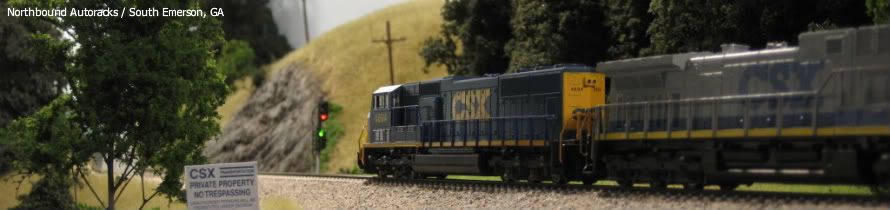
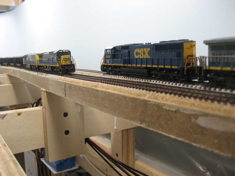
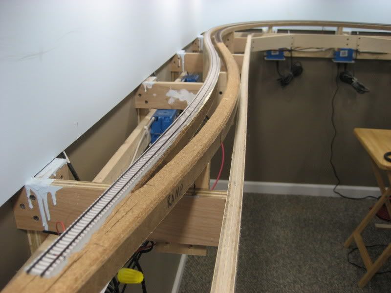
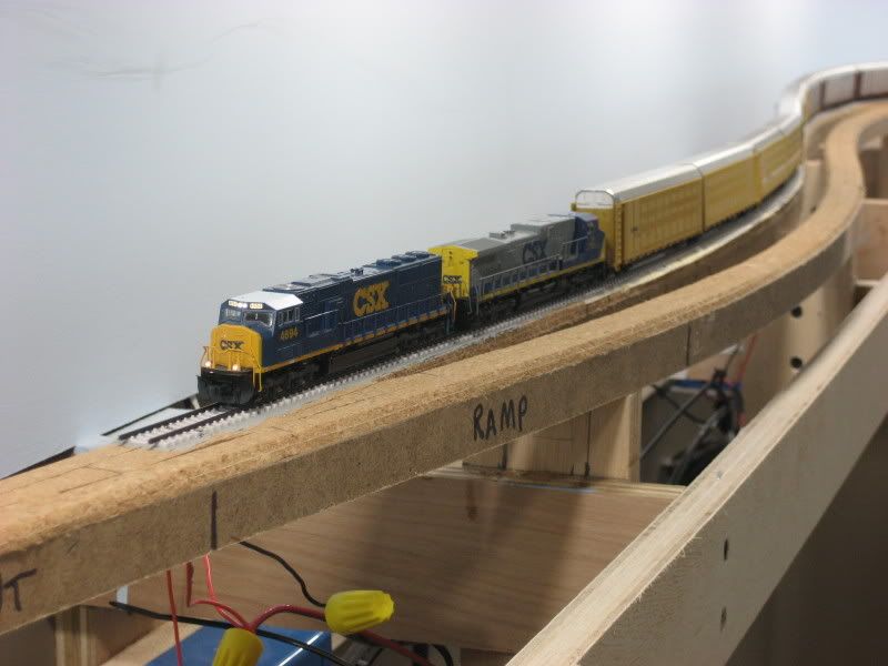
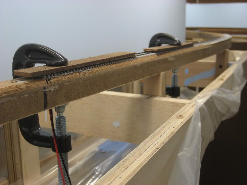
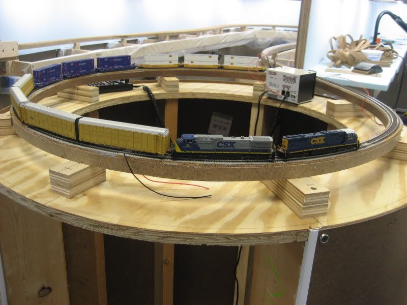
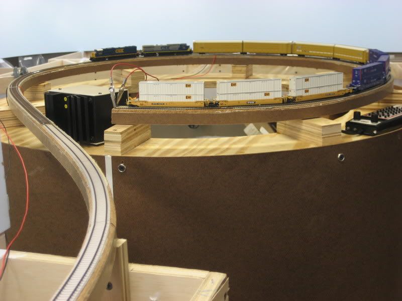
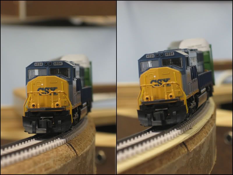
This post describes how I solder the feeder wires to the track on my N-Scale CSX Dixie Line layout. My soldering skills have been horrible in the past and are still not great, but I think I have devised a method that is almost completely goof-proof and results in feeder wires that will be completely hidden once the track is ballasted. The following photo shows a finished example of this technique:


The key to the success of my feeder soldering method is the use of Micro Engineering flex track with pre-weathered rail. I was not happy with this track when I first started using it, mostly because I am used to "springy" flex track like Atlas. However, the more and more I use the Micro Engineering flex track, the more I like it. In fact, since this track enables me to solder feeder wires without damaging or destroying the track, I have decided to switch completely to Micro Engineering code 55 flex track for all of my track with the exception of turnouts. I will continue to use Atlas code 55 turnouts.
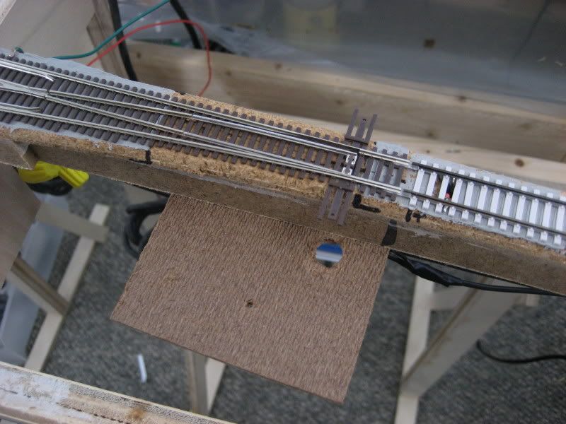
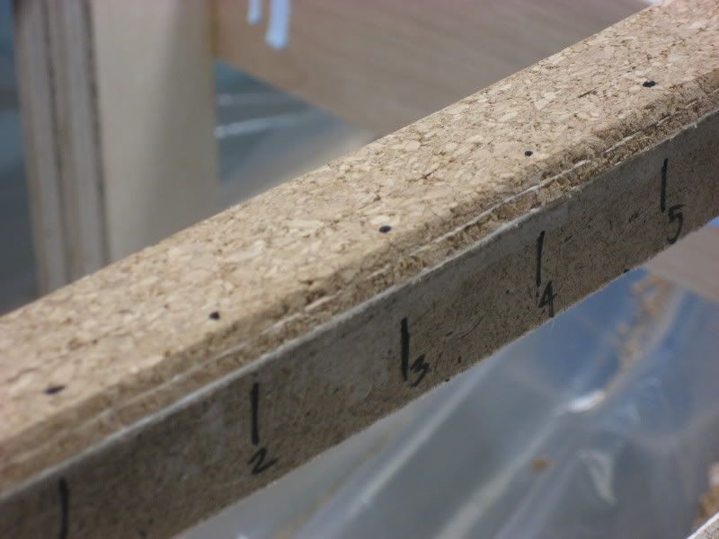
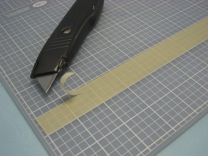
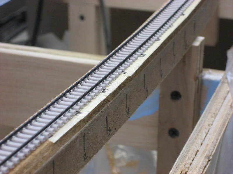
Step-by-Step

Step 1 I solder my feeders three ties in from the end of a section of flex track. I solder feeders to every piece of flex track because I will be leaving gaps between each piece of track to allow for expansion/contraction. When I solder the feeder wires to the bottom of the rails, I want to make sure they are soldered to a spot between a set of ties so that the tie spacing remains constant; the weathered rail makes it easy to mark the right spot. To do this, first cut away any plastic between the third and fourth tie in from the end of the track. This will allow access to both rails from below between the ties:


Step 2 
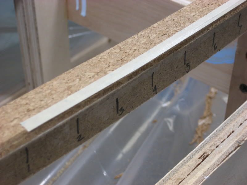
Next, using a small jewelers file, file the bottoms of both rails between the ties to remove the weathering:


Step 3 
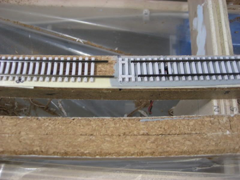
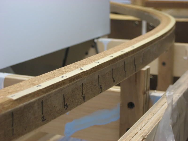
Finally, slide the three "outer" ties completely off of the piece of flex track. You also want to push the adjacent "inner" ties inward so they will not be affected by the heat of the soldering iron. I cut gaps between the adjacent four inner ties and pushed them inward, away from the spots where the feeders will be soldered:


Step 4 
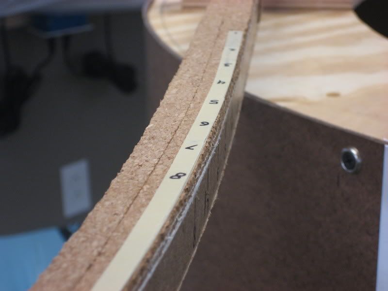
Next, tin the feeder wires and the spots on the rails that were filed away in the previous step. I use 20 gauge solid wire for my feeders and strip about 1/8" of insulation off one end of each wire. I use black for the inner rail and red for the outer rail--be sure to be consistent throughout the layout to avoid short circuits. As for the rails, the use of weathered rails pays off big time with regards to tinning. Solder will only stick to clean metal, so in our case, the solder will stick to the filed away spots and will not stick to the weathered rail. This is perfect because it will allow us to slide the plastic ties back onto the rails right against the soldered feeders, keeping the tie spacing exactly as it was before.

I apply a tiny amount of flux gel to the filed spots in the rail and the bare wire ends. I then use a Weller 40-watt soldering iron with a flat chisel tip to heat the rail and apply a tiny bit of solder. I do the same thing with each feeder wire:


Important: The key to this step is to be quick. I hold the tip of the soldering iron to the rail and immediately apply the solder then quickly remove the tip from the rail. The whole process takes bout two seconds; any longer and you risk melting the nearby plastic ties. By sliding the ties away from the spots on the rails to be soldered, you get a nice safety margin and I have yet to damage any ties when soldering track this way. I also found that by using the Weller 40-watt iron (which is a blowtorch when compared to the typical 25- or 30-watt soldering iron you get off the shelf at Radio Shack), you can heat the rail/wire very quickly and get the solder to flow within a second or two. This means you can get out before the heat reaches the plastic ties.

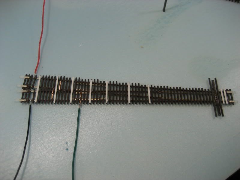
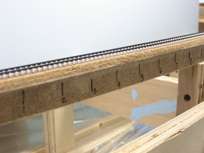
Important: You can see where I made black marks along one edge of the ties. This is to remind me which rail is to have the black feeder wire soldered to it. It is very easy to get the rails reversed when you flip over a piece of track, so I always mark one side of the ties before I start soldering.

Note: You can see a few drops of liquid and some areas that appear wet in the above photo. This is actually the residue of the flux gel that I use when soldering. The gel turns to liquid when heat is applied and the soldered areas can get a bit messy with this goo. However, cleanup is very simple as I just use an old toothbrush wet with 70% rubbing alcohol to scrub the area after all the soldering work has been completed. This removes all residue from the soldering process.

Step 5 Once the track and wires have been tinned, it is a piece of cake to solder the wires to the rails. Simply hold the tinned end of one wire against the tinned spot on one rail and apply heat until the solder flows. Repeat with the other wire:


Step 6 
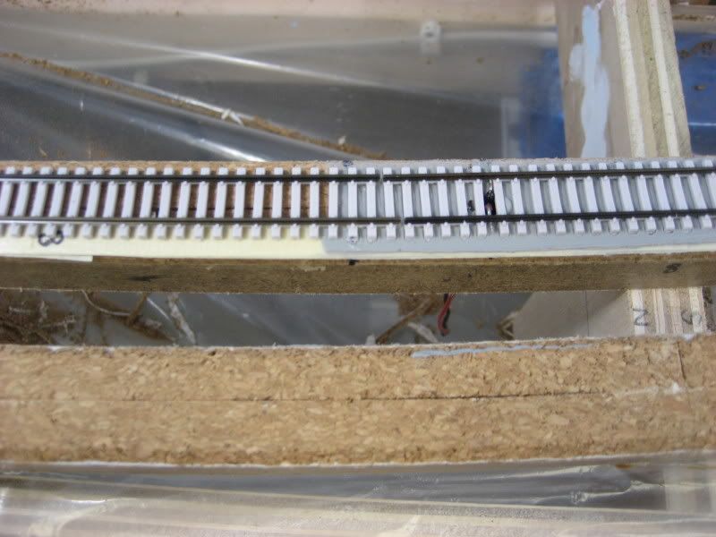
Finish the process by scrubbing the work with the toothbrush dipped in rubbing alcohol and sliding the plastic ties back in place:


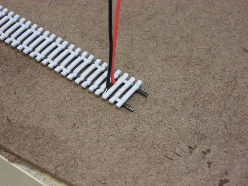
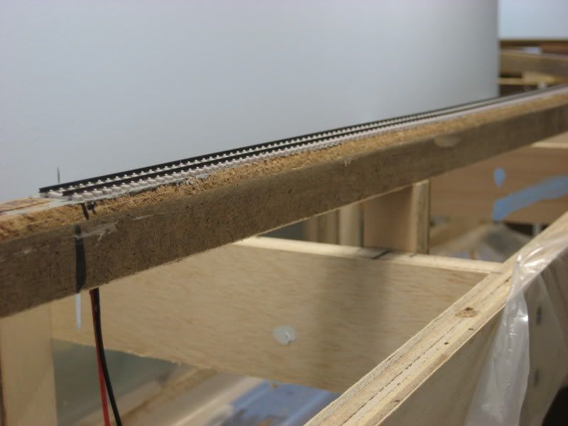
You now have a piece of flex track with feeder wires that is ready to be installed on the layout:


.

Tuesday, April 7, 2009

DIY: Superelevate Track

All mainline curves on the CSX Dixie Line layout will be superelevated. Superelevation is the prototype practice of elevating the outside rail to combat the centrifugal forces imposed on a speeding train as it rounds a curve. Model railroads do not need to worry about such forces, but the visual impact of watching a modern locomotive lean into a curve is just too much for me to resist! To see what I mean, take a look at this photo taken of two eastbound trains waiting for a signal on the CSX Kanawha Sub in St. Albans, WV:


The train on the left is on the flat siding track while the train on the right is on one of the superelevated main tracks. I believe superelevating curves on a model railroad is one of the simplest ways to boost realism on a layout. I am using the technique published in Model Railroader and documented by Michael Highsmith on his Ranier Great Western model railroad website. This technique uses narrow strips of regular masking tape placed under the outside rail of the curved track. I tried this technique out on my test layout and found the results to be outstanding, as you can see by this video I included in a previous post. The following steps show how I superelevated the first track installed on the actual CSX Dixie Line layout.

Step-by-Step

Step 1 Just as you must use easements when laying out curved track on your layout, you must also include vertical easements between the flat/level track and the superelevated track. The layered tape approach allows you to easily build these vertical transitions. First, you need to mark both ends of the superelevated curve on your roadbed. Then, starting at the ends of the curve and working in, make additional marks every one inch until you have eight marks on each end of the curve. This will indicate where each of the eight layers of tape should begin. In this picture, you can see where I have marked my roadbed (the curve starts at the #1 mark and continues to the right):


Step 2 I also marked a series of dots 3/16" from the track centerline along the superelevated curve. These marks indicate where the outside rail of my track is located and will be used to align the edge of the strips of masking tape:


Step 3 I then cut lengths of ordinary 1" wide painters masking tape into strips 1/4" wide. I selected a high tack masking tape so there would be good adhesion to the cork roadbed:


Step 4 I then began laying the strips of tape along the curve to be superelevated, starting at the #1 mark and with the inner edge of the tape aligned with the dots that denote the outside rail. Continue laying the first strip of tape until you reach the #1 mark at the opposite end of the curve:


Step 5 Start laying the she second strip of tape at the #2 mark and end at the opposite #2 mark, then repeat the process with all eight layers of tape. The staggered starts of each strip of tape are what creates the vertical easements. Here is a closeup of all eight layers at the start of my superelevated curve:


The tape continues around the curve:


The tape ends at the opposite end of the curve:


Step 6 The track can now be installed with the outside rail aligned with the inside edge of the layers of tape. The excess tape will be trimmed away after the track has been permanently fastened to the roadbed:


Here is a side-by-side comparison showing a train on the curve both before and after the superelevation that was performed in the above steps:


.