This post includes a detailed step-by-step account of how I made my own cork roadbed for my N-scale CSX Dixie Line layout. I chose homemade cork roadbed over the commercially available products because I wanted to vary the thickness of the roadbed on my mainlines and sidings. I considered using two layers of standard N-scale cork roadbed for my mainline, but that would have been too thick. I also considered using standard HO-scale cork roadbed for my mainline and N-scale cork roadbed for my sidings, but I did not think that would not have been enough of a difference between the heights of the two roadbeds. To give a visual reference of what I am trying to accomplish, take a look at this picture that shows the mainline and siding of the CSX W&A sub through Emerson, Georgia:

In this photo, notice the much higher ballast profile of the main track at the far left compared to the siding track in the center. The house track to the right does not even have a ballast profile. This is the effect I am trying to duplicate on my layout.
For my custom cork roadbed, I purchased
The Board Dudes #268 Hobby Cork Roll from Hobby Lobby. This package contains a solid sheet of 3/16" thick natural cork material 2 feet wide by 8 feet long. I also found rolled sheet cork at Michael's Crafts and Ace Hardware, but the product at Hobby Lobby was the ideal size and also had the lowest price. Since my cork roadbed will be 1 inch wide, this roll will yield 24 strips of roadbed 8 feet long, or 192 linear feet of 3/16" thick roadbed. Even when stacking two strips of roadbed to produce a 3/8" height, you will still yield 96 linear feet of roadbed--not bad for a $15 roll of cork!
Aside from wanting to vary the thickness of my roadbed, I also wanted to customize the width of my roadbed. I found that commercially available N-scale roadbed--both cork and foam--is just way too wide for my liking. When I place a piece of flex track on a piece of store bought cork or foam roadbed, there is a really wide shoulder between the outside of the ties and the beveled edge of the roadbed. By contrast, most of the prototype photos I reviewed shows that the ballast begins sloping down immediately outside of the ties. Of course this arrangement is not always the case, but it certainly seems to be the practice along the lines I am modeling. I could just narrow down the commercially available roadbed, but if I am going to make all of these cuts anyway, why not just start out from scratch?
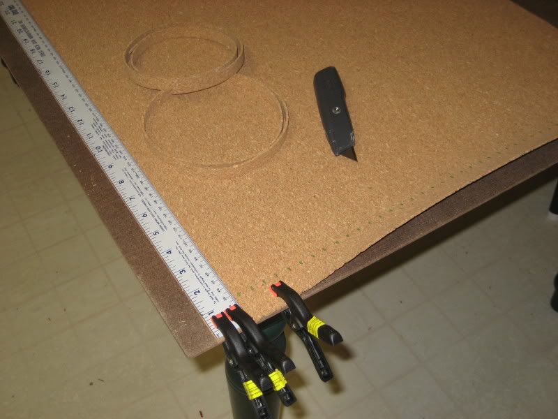
Step-by-Step InstructionsStep 1 As mentioned above, I first cut the 8' long roll of cork sheet into three equal lengths (32" long each). This made the cork easier to work with when cutting into strips. Although my roadbed is 1" wide, I cut 48 1/2" wide strips out of each 32" long sheet of cork. When laying the roadbed, the 1/2" width makes it much easier to fit the roadbed around curves. I cut my cork on the kitchen table, first laying down a scrap sheet of Masonite hardboard to protect the table. Spring clamps helps to hold the cork in place:
 Step 2
 I used a standard utility knife to make the cuts along a metal ruler used as a straight edge. The 1/2" wide strips of cork will curl up since they have been rolled tightly:
 Step 3
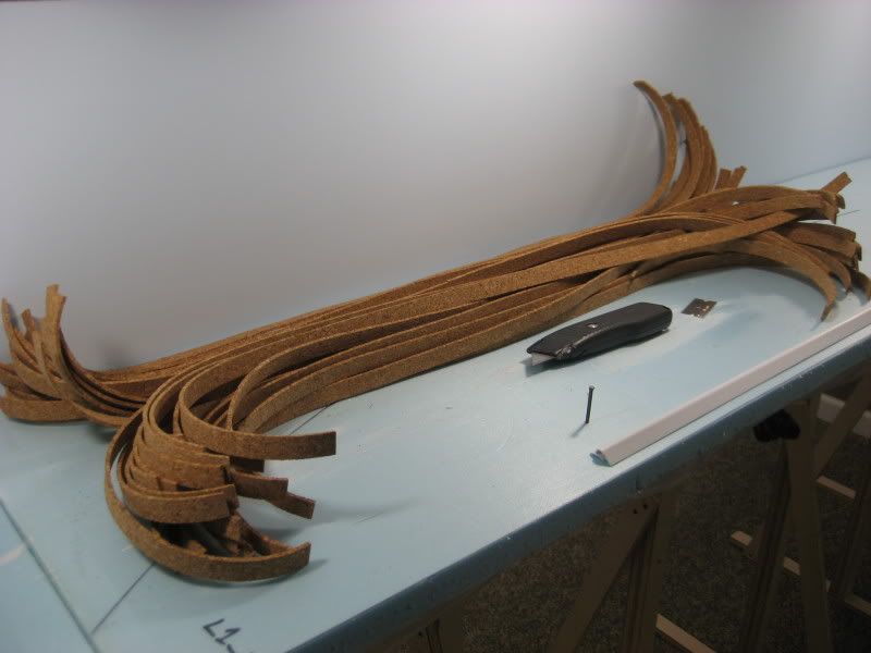
 Once all of the strips have been cut from the sheet of cork, I placed them together in a bundle and set the entire bundle in a spot on the layout close to where I will be installing the roadbed:
 Step 4
 For fastening the cork to the top of my spline roadbed, I used DAP ALEX Plus acrylic latex caulk. I used the Easy Caulk variety that comes in a spray can and eliminates the need for a caulking gun:
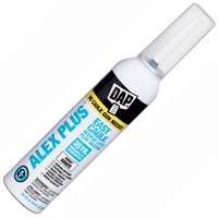
The Easy Caulk is more expensive than the cartridges that go in a caulk gun, but I found that the "caulk in a can" gives much better control and the tip is much easier to clean and reseal. To begin, I cut the nozzle along the smallest score line and laid a bead of caulk about 3 feet long where I wanted to start installing my roadbed:
 Tip: You may want to practice laying a bead of caulk on some scrap material to get a feel for how to control the flow of the caulk. If you press too hard on the nozzle, the stuff will squirt all over the place. This happened to me, but fortunately the goop missed my backdrop (just barely!) and landed on a scrap piece of foam board.Step 5
 Using a regular putty knife, spread the bead of caulk so it covers the entire surface of the spline roadbed (or whatever your cork will be sitting on). Try to spread the caulk as thin as possible while maintaining even coverage--this step is a lot like icing a cake:

Unless you spread the caulk perfectly, you will get a lot of gobs of the stuff on the side of the spline roadbed. This is not a big deal since it is easy to remove once it has dried. In fact, we will shave off any of the dried gobs of caulk when we come back later to trim down the width of the cork.
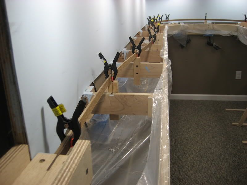
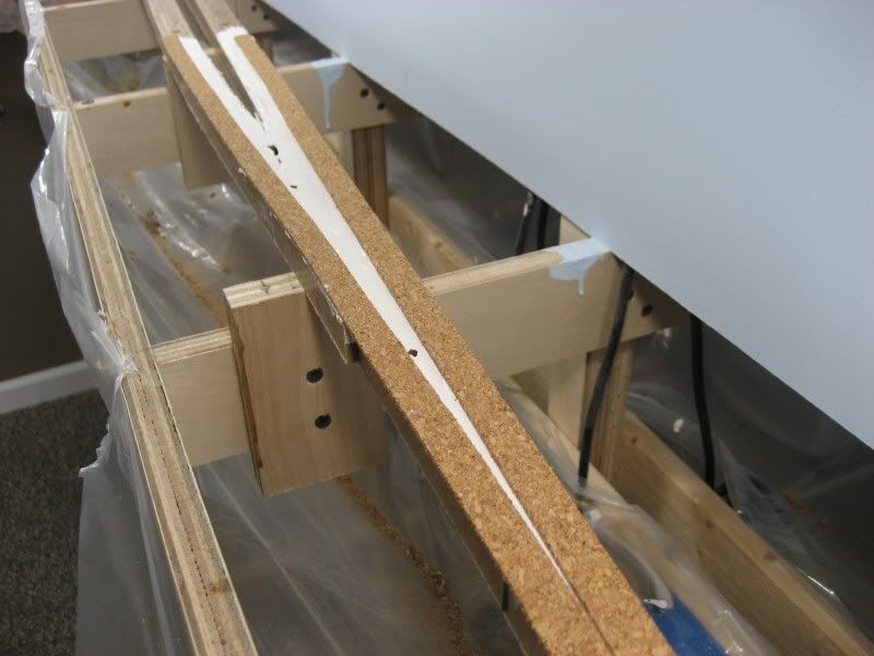
Step 6 Lay down one 1/2" wide strip of the cork into the caulk on top of the spline roadbed. You want to make sure that the inside edge of the cork follows the track centerline, which in my case was the center of the middle spline in my roadbed:
Don't worry if the outside edge overhangs the outer spline; this will get trimmed down later. Just start at one end of the strip of cork and keep the inside edge following the track centerline until you have the entire strip laid down into the caulk. I had planned on using push pins to keep the cork in place but found that the caulk had plenty of grab to keep the cork right where I laid it, even around my tightest 15" radius curves.
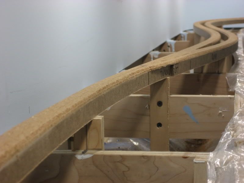
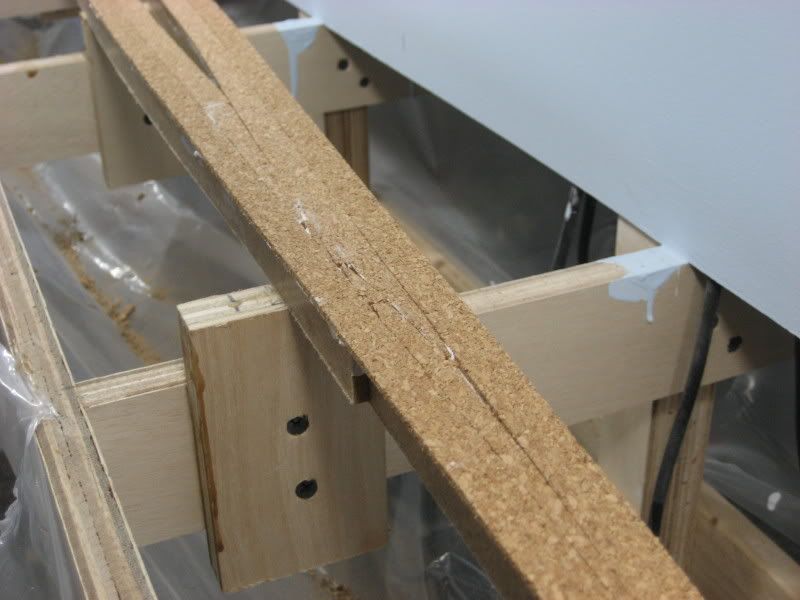
Tip: Remember how the strips of cork are curvy from being coiled up on the roll? When laying the strip of cork into the wet caulk, be sure to place it curvy side down. If you do not do this, the ends of the strip will want to curl up and you will need to secure each end with a push pin or a weight. When laying strips curvy side down, I never had to use anything to keep the edges from curling.Step 7 Lay another strip of cork into the wet caulk, using the previously laid strip to align the new piece. When you have done this, the seam between the two adjacent strips of cork will provide a perfect centerline for laying your track:
 Step 8
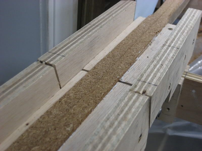
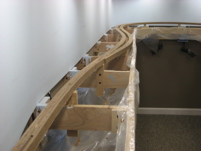
 When encountering a turnout, lay and spread the bead of caulk beyond both legs of the turnout. When laying the pair of adjacent cork strips, lay one along each leg of the turnout being sure to keep the inner edge of the cork strips aligned with the track centerline:
 Step 9
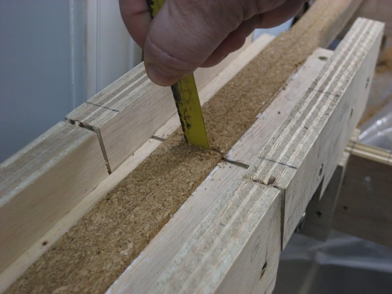
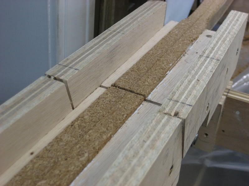
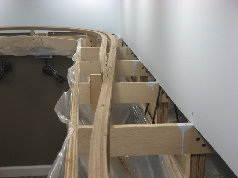
 Finally, starting from the far end of each leg of the turnout (where the previous two strips ended), lay two more strips of cork back towards the turnout. Fill in the remaining "bare spots" with triangular pieces of cork cut from a scrap strip:
 Step 10
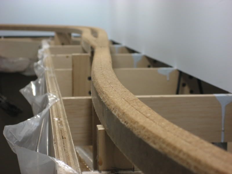
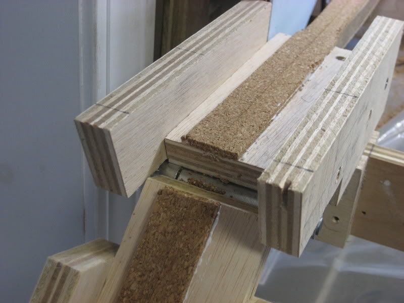
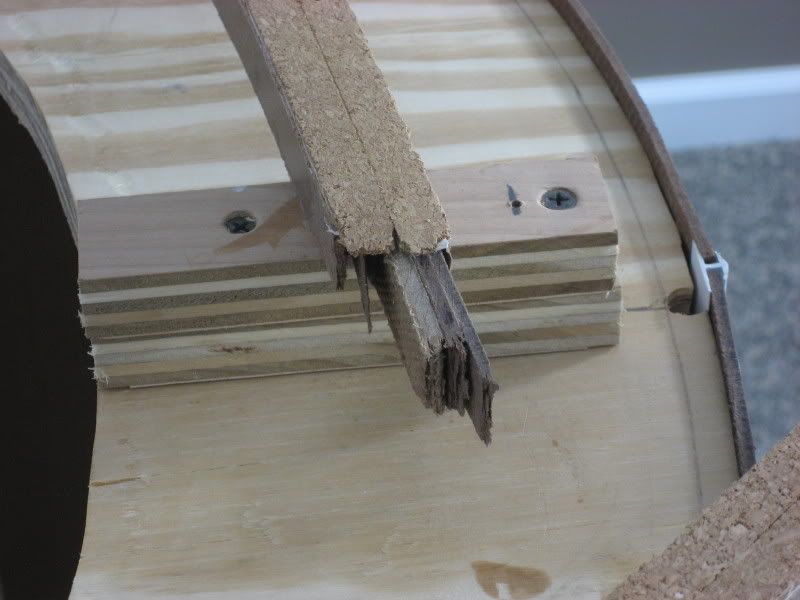
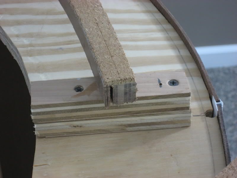
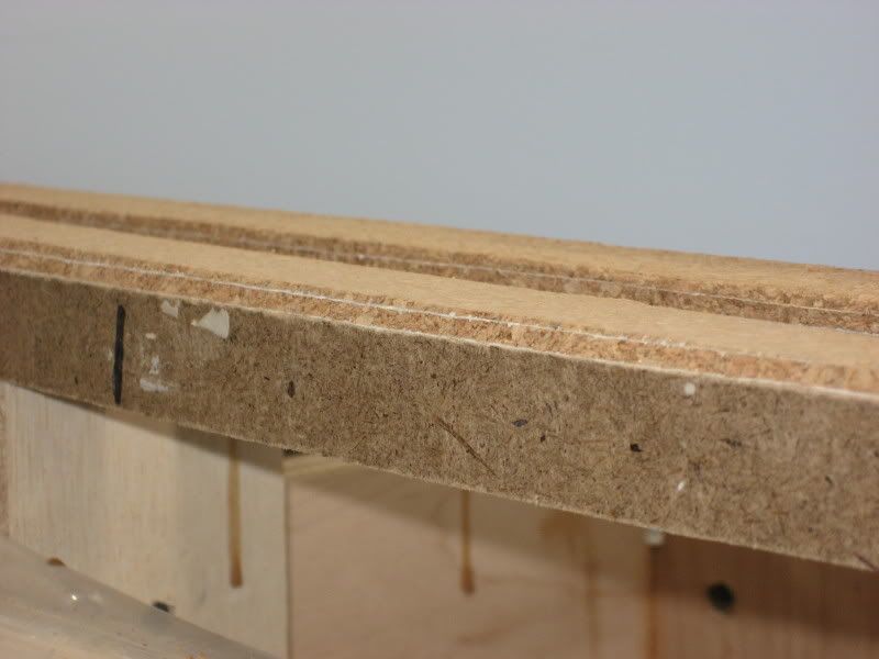
 For any mainline track, add a second layer of 3/16" cork over the first layer. This will give your mainline track a nice high 3/8" ballast profile. For the sidings, you will need to lay the double layer of cork a short distance into the siding. I laid the second layer of cork a full 12" beyond the end of the turnout for the siding:
 Step 11
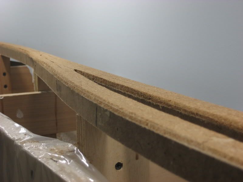
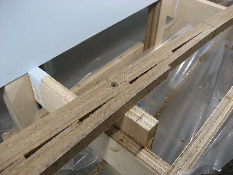
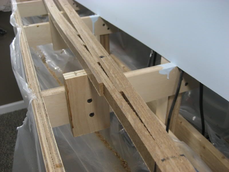
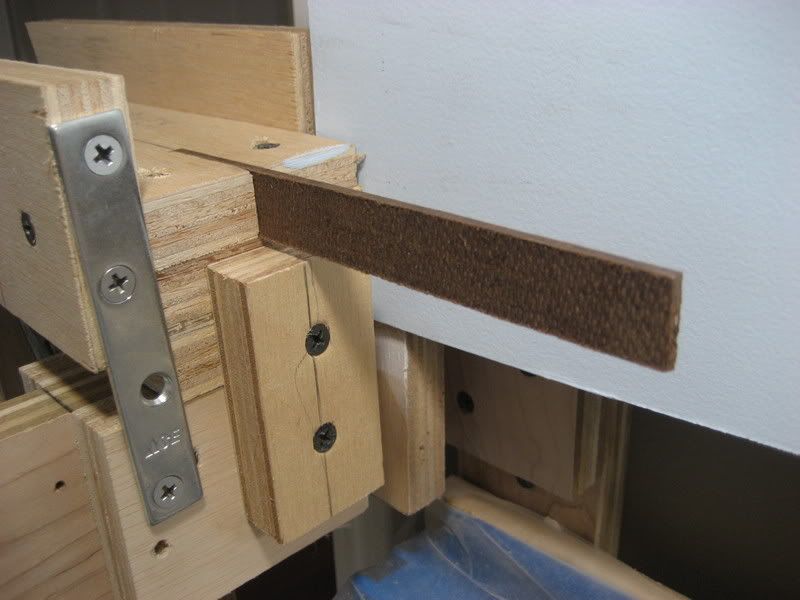
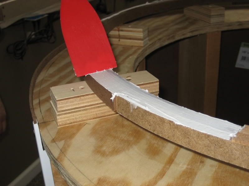
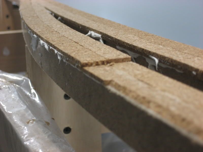
 Using a sanding block loaded with 150 grit sandpaper, I sanded a transition ramp into the short section of second cork laid into the siding. This provides a nice, smooth transition in the track from the lower height of the siding to the higher height of the mainline. In this picture, you can see how the cork roadbed has been sanded to provide a nice smooth transition from the higher mainline at the left down to the lower siding at the right:
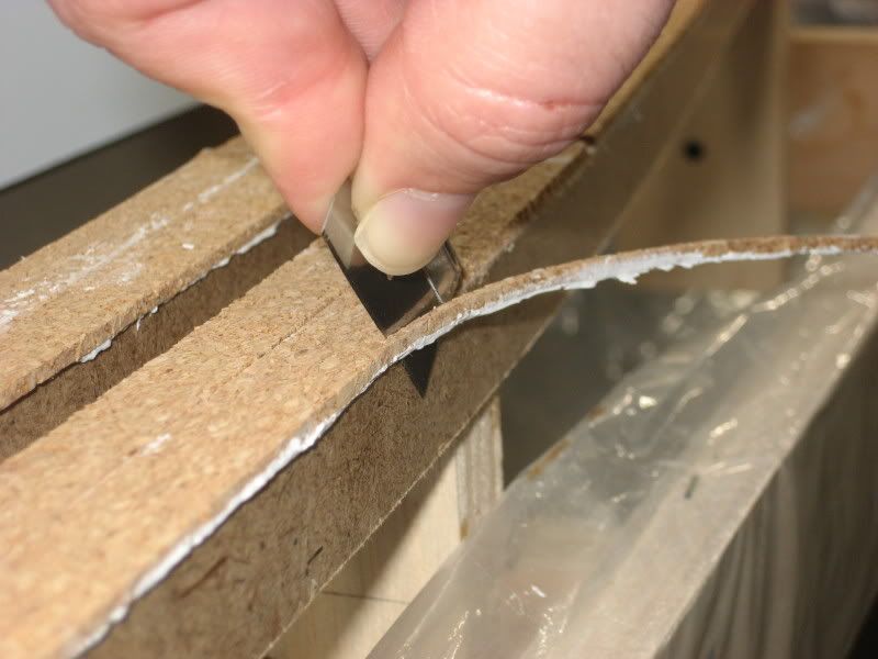
 Step 12
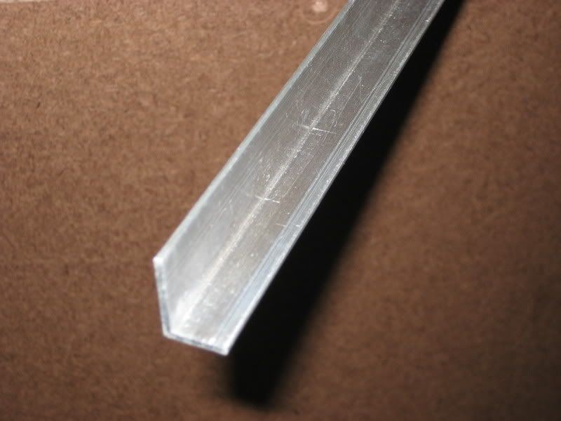
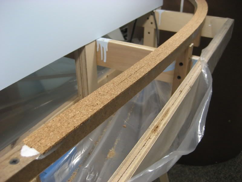
 After the caulk has completely dried (I allowed 24 hours), the outside edge of the cork roadbed needs to be trimmed to be even with the outside edge of the spline roadbed. The cork roadbed is 1" wide while the spline roadbed is only 15/16" wide, so there will be a bit of overhang to trim away. I use a single edge razor blade to do this trimming. I hold the blade vertically pressed against the outside of the spline roadbed as a guide, then trim away the excess cork using a sawing motion:
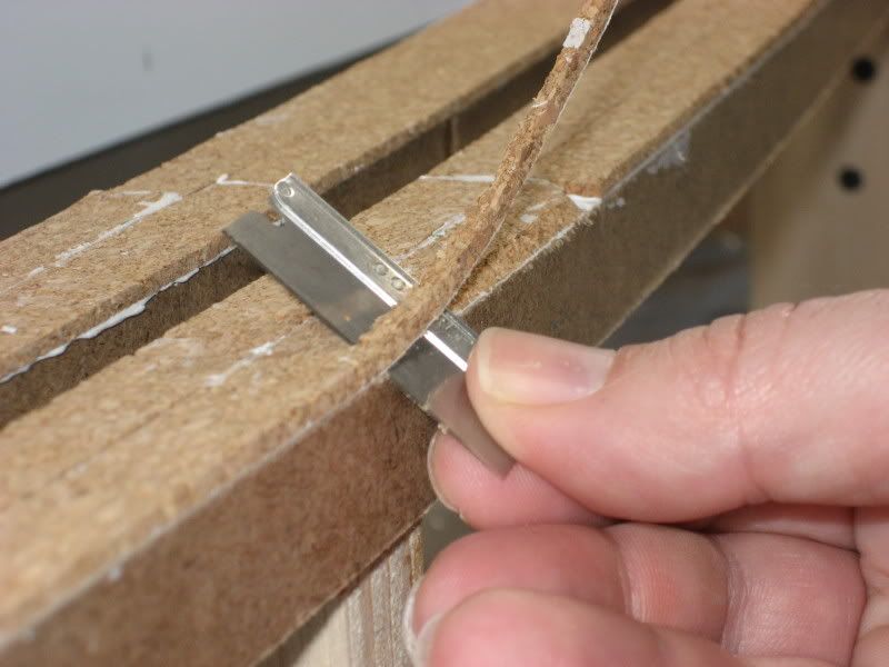
 Step 13
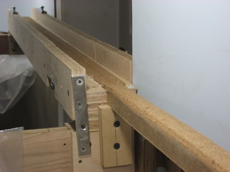
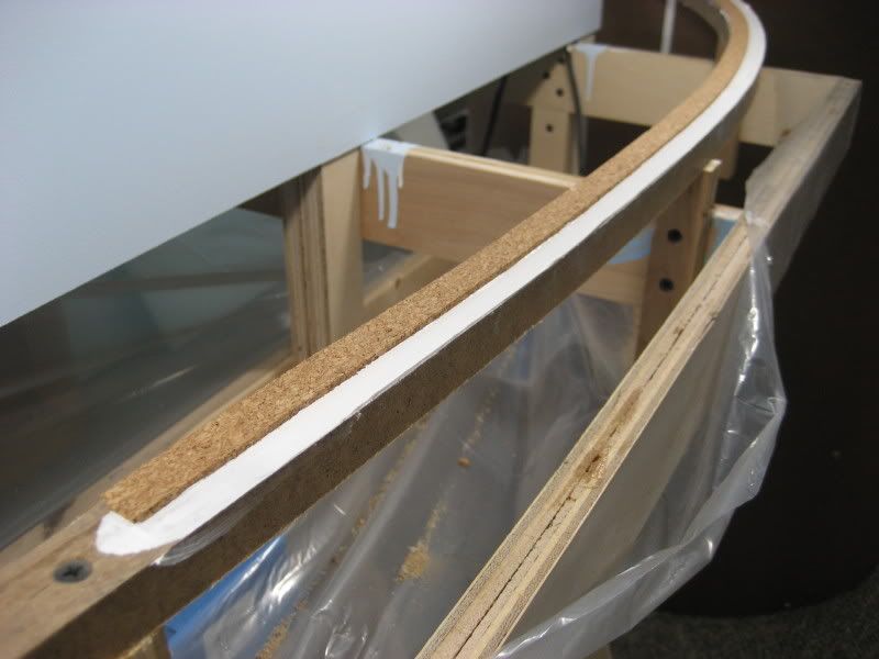
 The edge of the cork roadbed needs to be bevelled to match the shape of the ballast profile. For this cut, I use the same single edge razor blade and the same motion as in the previous step, except that I hold the blade at about a 45 degree angle:
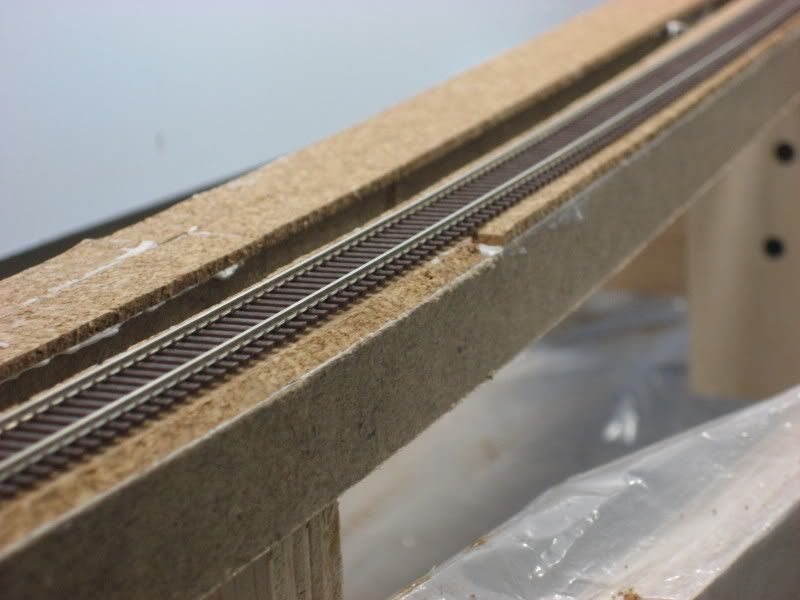
You want the bevel to begin just outside the ties of a piece of track. I have set a piece of Atlas code 55 flex track in place to show how this should look (notice that the cork roadbed in the distance has not yet been bevelled):
 Step 14
 Using a sanding block loaded with 150 grit sandpaper, I
very gently sand the top of the cork roadbed:
 Important: Remember that the natural cork material is very soft, so it is easy to overdo the sanding. All you want to do here is knock down any slight bumps or ridges so the track will have a nice flat, smooth mounting surface.
After installing, trimming and sanding the cork roadbed, you will have a nice sturdy, smooth and quiet surface that the track can be mounted on. When the track is ballasted, you will have a realistic high ballast profile for the main track and a lower ballast profile for any sidings. Industrial tracks and spurs will be laid directly on the roadbed where appropriate for an even better effect.
.